
A non-stop intelligent phase splitter for AC electrified railway

A technology for electrified railways and phase splitters, applied in power lines, vehicle components, transportation and packaging, etc., can solve the problems of high cost, difficulty, and large traction current of twisted-pair insulated cables, and reduce construction difficulty and fixed investment Cost, low cost effect

Active Publication Date: 2020-06-02
BEIJING EFFICIENGINE TECH LLC +1
View PDF7 Cites 0 Cited by
  • Summary
  • Abstract
  • Description
  • Claims
  • Application Information

AI Technical Summary

Problems solved by technology

However, due to the large traction current of the train, it is difficult to use twisted-pair insulated cables for the connection line of the transfer switch in actual operation.
The high cost of twisted-pair insulated cables is also not conducive to the promotion of non-tunnel, elevated and other applications

Method used


Image

  • A non-stop intelligent phase splitter for AC electrified railway
  • A non-stop intelligent phase splitter for AC electrified railway
  • A non-stop intelligent phase splitter for AC electrified railway

Examples


Embodiment 1

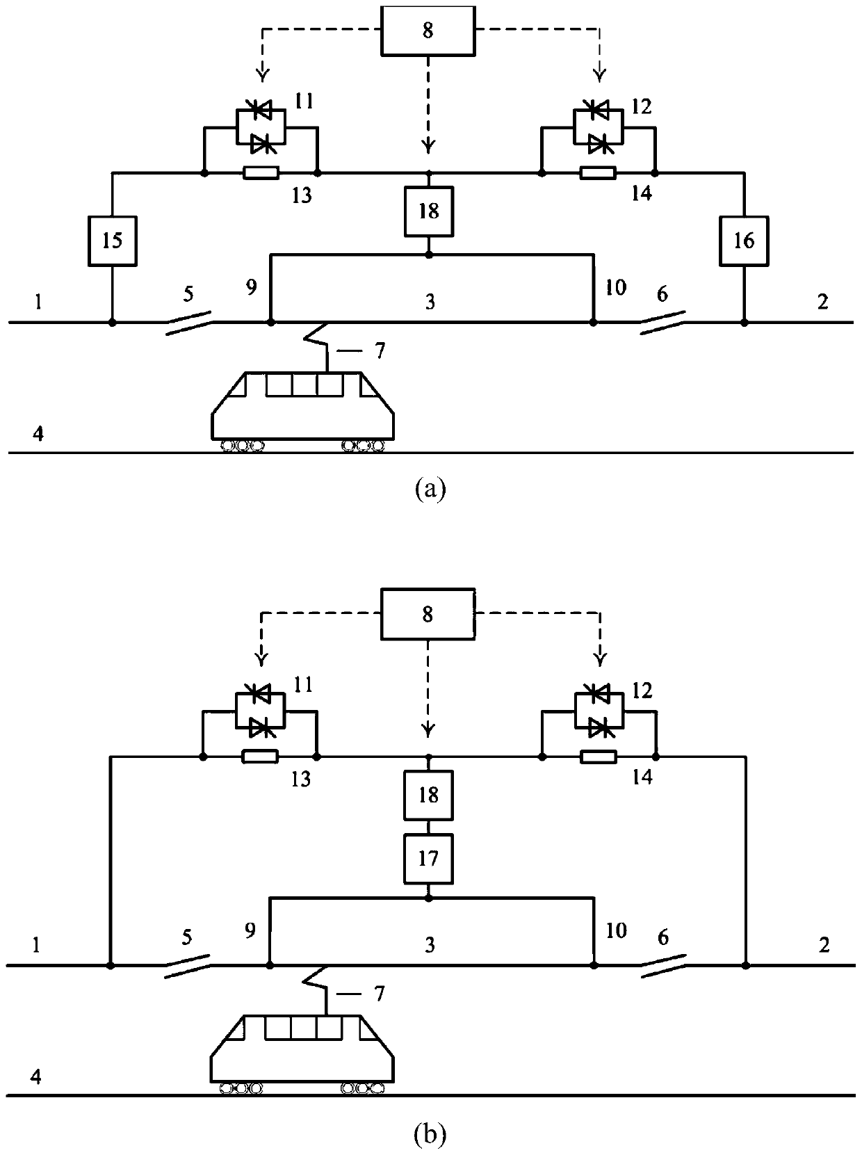
[0041] see figure 1 (a), the AC electrified railway non-stop intelligent phase splitter of the present invention comprises two fast switches 11, 12 and parallel impedances 13, 14 at both ends thereof, two arc-extinguishing adjustable power supplies 15, 16, and a step-shift phase shifter Power supply 18, two connecting wires 9 and 10 in the neutral zone, two fast switches and connecting wires between the arc-extinguishing adjustable power supply and the power supply arm, and an intelligent phase splitter control unit 8 with the function of identifying the position of the train pantograph; A current sensor is installed on each quick switch 11,12 and each neutral zone connection wire 9,10; a voltage sensor is installed on each quick switch 11,12 both sides.

[0042] The current sensor, voltage sensor, and fast switches 11, 12 installed in the above device, the drive control unit of the arc-extinguishing adjustable power supply 15, 16 and the step-shift power supply 18 are all con...

Embodiment 2

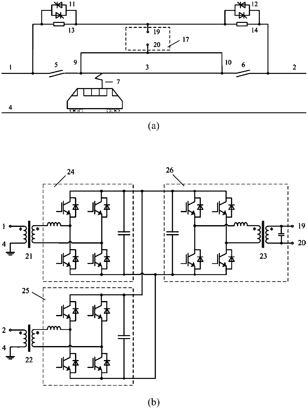
[0050] see figure 1 (b), the AC electrified railway non-stop intelligent phase splitter of the present invention comprises two fast switches 11,12 and parallel impedances 13,14 at both ends thereof, an arc-extinguishing adjustable power supply 17, a step-shifting power supply 18, two The connecting wires 9 and 10 in the neutral area, the connecting wires between the two quick switches and the power supply arm, and the intelligent phase splitter control unit 8 with the function of recognizing the position of the train pantograph; each quick switch 11, 12 and each neutral Current sensors are installed on the connecting wires 9 and 10 in the district; voltage sensors are installed on both sides of each quick switch 11 and 12.

[0051] The current sensor, voltage sensor, and fast switches 11 and 12 installed in the above device, the arc-extinguishing adjustable power supply 17, and the drive control unit of the step-shift power supply 18 are all connected to the intelligent phase ...

Embodiment example 1

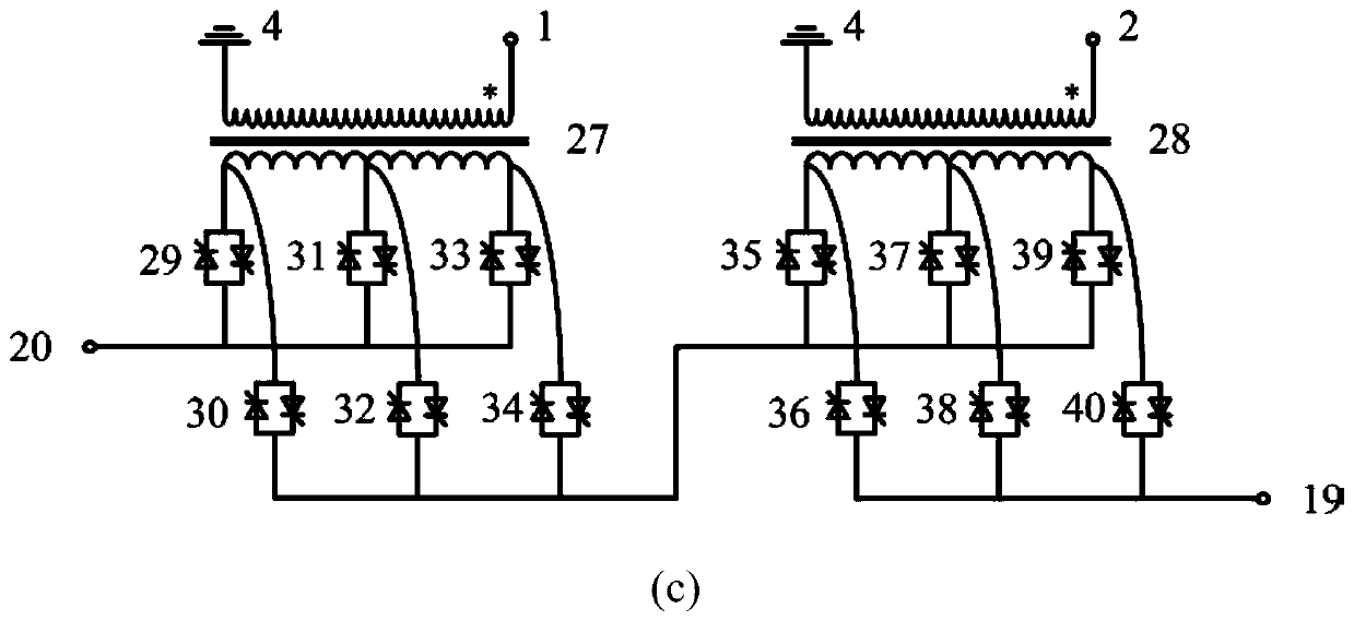
[0069] In the first implementation case, the step-shift power supply can generate an intermediate voltage whose two phases are between the voltage of the first power supply arm 1 and the voltage of the second power supply arm 2, such as image 3 (a) shown. In this implementation case, the topological circuit of the stage-shifted power supply 18 includes two input transformers 41, 42, four transfer switches 43, 44, 47, 48, and parallel impedances 45, 46 at both ends of the transfer switches 43, 44; Voltage sensors and current sensors (not shown in the figure) are all installed on the transfer switches 43, 44, 47, 48. The current sensor installed in the above device, the voltage sensor, the drive control unit of each transfer switch 43, 44, 47, 48 are all connected with the intelligent phase splitter control unit (not shown in the figure).

[0070] The working process of the step phase-shifting power supply 18 implementation case one of the present invention is as follows:

[...


PUM


Abstract

The invention discloses an alternating current electrified railway uninterrupted intelligent phase splitter. The alternating current electrified railway uninterrupted intelligent phase splitter comprises two high-speed switches, an arc extinction adjustable power supply, a neutral zone voltage transition step phase-shift power supply and an intelligent phase splitter control unit with a train pantograph type current collector position identifying function. The intelligent phase splitter control unit can determine positions of train pantograph type current collectors in overlapping sections andneutral zones on the two sides according to voltage and current information in the device. The arc extinction adjustable power supply is connected to a first high-speed switch circuit or a second high-speed switch circuit in series so that most currents of all pantograph type current collectors in the overlapping sections and the neutral zones flow through the first high-speed switch or the second high-speed switch to suppress or eliminate electric arcs of the train pantograph type current collectors during entering or leaving the neutral zones. The step phase-shift power supply can generatemultiple different intermediate voltages with phases between a first power supply arm voltage and a second power supply arm voltage so as to guarantee that the train is stably transitioned from a first power supply arm section to a second power supply arm section without being powered off.

Description

technical field [0001] The invention relates to the technical field of over-phase separation of electrified railways, in particular to a device for electrified over-phase separation of trains controlled by ground switches of AC electrified railways. Background technique [0002] my country's AC electrified railway mainly adopts single-phase power frequency commutation power supply. In order to avoid phase-to-phase short circuit, a catenary with electrical segments at both ends is installed at the exit of the traction substation and the partition booth, that is, the electrical phase separation. The electrical split phase is mainly divided into two types: device type and joint type, and the joint type is the majority. The articulated electrical separation phase consists of a neutral zone and anchor joints at both ends. Since the neutral zone catenary itself is not charged, when the train passes, the on-board equipment or the ground device need to perform special operations. ...

Claims


Application Information

Patent Timeline
Patent Type & Authority Patents(China)
IPC IPC(8): B60M3/04
CPCB60M3/04
Inventor 郑琼林杨景熙游小杰郝瑞祥黄鹭鹭杨晓峰孙湖
Owner BEIJING EFFICIENGINE TECH LLC
Learn More