
Ice-breaking rotor units, offshore foundations and offshore wind turbines

A technology for wind turbines and rotor units, which is applied in infrastructure engineering, construction, artificial islands, etc., can solve problems such as fatigue, damage to the foundation structure of offshore wind turbines, and foundation fatigue loads, and achieve the effect of high breakage rate.

Active Publication Date: 2021-04-27
JIANGSU GOLDWIND SCI & TECH CO LTD
View PDF3 Cites 0 Cited by
  • Summary
  • Abstract
  • Description
  • Claims
  • Application Information

AI Technical Summary

Problems solved by technology

The foundation of offshore wind turbines is generally several kilometers to tens of kilometers away from the land. If the wind turbines are installed in the northern seas, the floating ice on the sea surface will impact and impact the foundations of offshore wind turbines during the winter freezing period in the north. The basic structure of the wind turbine is damaged. When the ice floe hits the foundation and the ice floe itself breaks and breaks, new periodic shock vibrations will be generated. Long-term vibration will cause fatigue. When the periodic shock of ice shattering and offshore wind power generation When the frequencies of the foundation of the unit and the tower itself overlap, periodic resonance will occur, which is very unfavorable to the safety of offshore wind turbines
[0003] The existing anti-ice-breaking device is generally called anti-ice cone, which is a spindle structure, similar to the docking of two conical objects. It also uses the movement of the ice itself, and the ice cubes move along the upper cone surface or the lower cone surface, and the ice cubes are squeezed. The disadvantage of this structure is that it is heavy after crushing. The anti-ice cone installed on a steel pile of about 5 meters weighs nearly 100 tons.
Moreover, the ice-breaking device of this structure is also a passive ice-breaking device. The ice block is only hit once. It is possible that the ice block is not completely broken, but only moves up or down. The ice-breaking effect is not very good, and it will still hit the foundation. Cause the foundation to resonate, generate fatigue load on the foundation, and seriously cause the foundation to break and collapse

Method used


Image

  • Ice-breaking rotor units, offshore foundations and offshore wind turbines
  • Ice-breaking rotor units, offshore foundations and offshore wind turbines
  • Ice-breaking rotor units, offshore foundations and offshore wind turbines

Examples


Embodiment Construction

[0032] Features and exemplary embodiments of various aspects of the invention will be described in detail below. In the following detailed description, numerous specific details are set forth in order to provide a thorough understanding of the present invention. It will be apparent, however, to one skilled in the art that the present invention may be practiced without some of these specific details. The following description of the embodiments is only to provide a better understanding of the present invention by showing examples of the present invention. In the drawings and the following description, at least some well-known structures and techniques have not been shown in order to avoid unnecessarily obscuring the present invention; and, for clarity, the dimensions of some structures may have been exaggerated. Furthermore, the features, structures, or characteristics described hereinafter may be combined in any suitable manner in one or more embodiments.

[0033] The orient...


PUM


Abstract

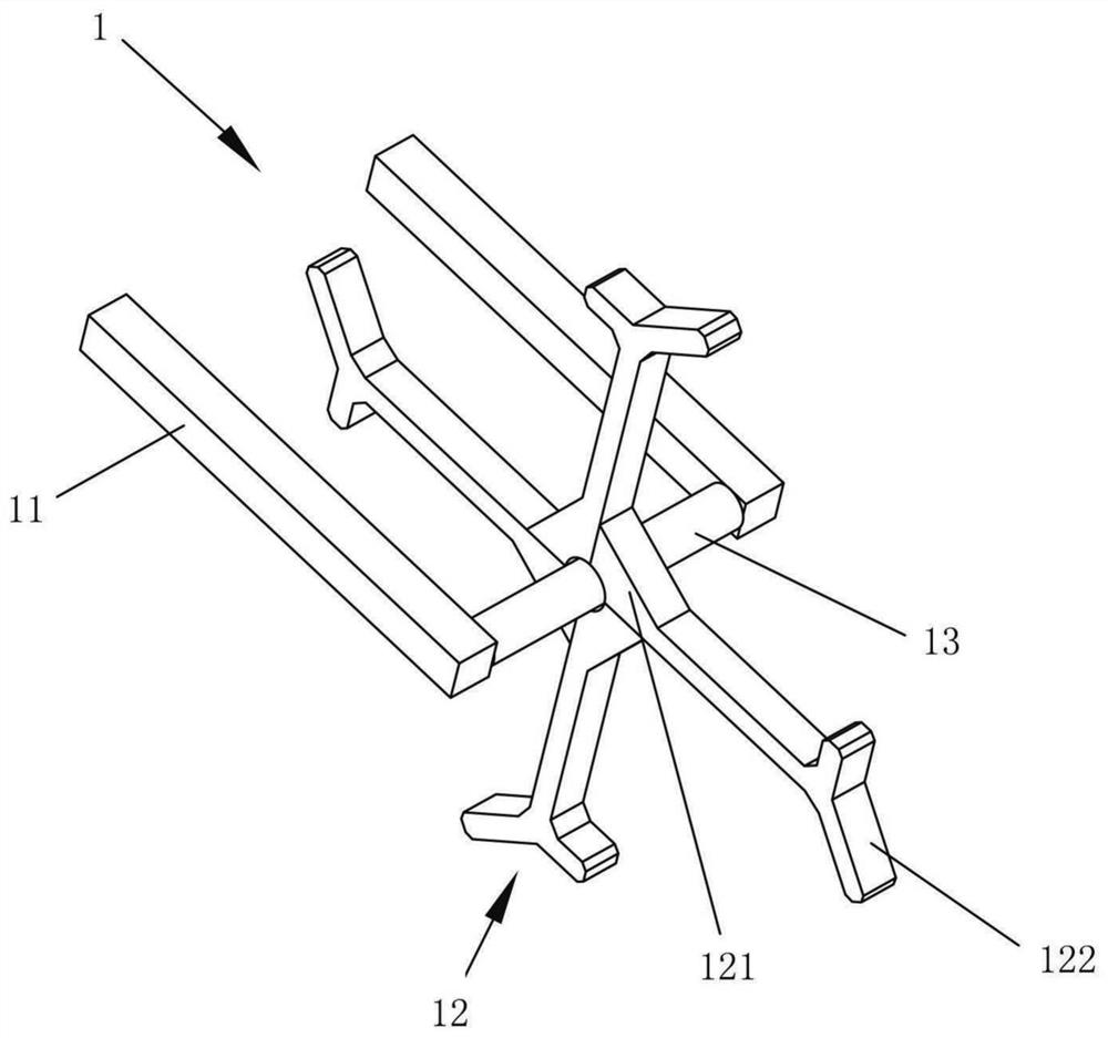
The invention relates to an ice-breaking device, an offshore foundation and an offshore wind power generating set, comprising an ice-breaking rotor unit (1), including an ice-breaking rotor bracket (11) fixed on the outer wall of the foundation, and an ice-breaking rotor bracket (11) is installed between the ice-breaking rotor brackets (11) Rotatable active ice-breaking rotor (12). When the entire block of ice moves to the ice-breaking rotor unit (1), the ice-breaking rotor (12) is driven by the motion of the ice, and actively rotates without additional power drive, continuously breaks ice, and has a high crushing rate.

Description

technical field [0001] The invention relates to the technical field of wind power, in particular to an ice-breaking rotor unit, a foundation and an offshore wind power generating set. Background technique [0002] With the rapid development of offshore wind power generation, high-latitude cold sea areas have attracted more and more attention because of their high wind energy density. The foundation of offshore wind turbines is generally several kilometers to tens of kilometers away from the land. If the wind turbines are installed in the northern seas, the floating ice on the sea surface will impact and impact the foundations of offshore wind turbines during the winter freezing period in the north. The basic structure of the wind turbine is damaged. When the ice floe hits the foundation and the ice floe itself breaks and breaks, new periodic shock vibrations will be generated. Long-term vibration will cause fatigue. When the periodic shock of ice shattering and offshore wind...

Claims


Application Information

Patent Timeline
Patent Type & Authority Patents(China)
IPC IPC(8): E02B17/00E02D27/44E02D27/52
CPCE02B17/0017E02B17/0021E02D27/44E02D27/52
Inventor 陈金龙杨勇方晶
Owner JIANGSU GOLDWIND SCI & TECH CO LTD
Learn More