

Barrel-shaped foundation capable of weakening soil plug phenomenon
A barrel-shaped foundation and phenomenon technology, which is applied to the barrel-shaped foundation field of marine engineering, can solve problems such as increasing construction difficulty and increasing construction costs, and achieves the effects of low price, reduction of hydraulic gradient, and elimination of soil plug phenomenon.
- Summary
- Abstract
- Description
- Claims
- Application Information
AI Technical Summary
Problems solved by technology
Method used
Image

Examples
Embodiment Construction
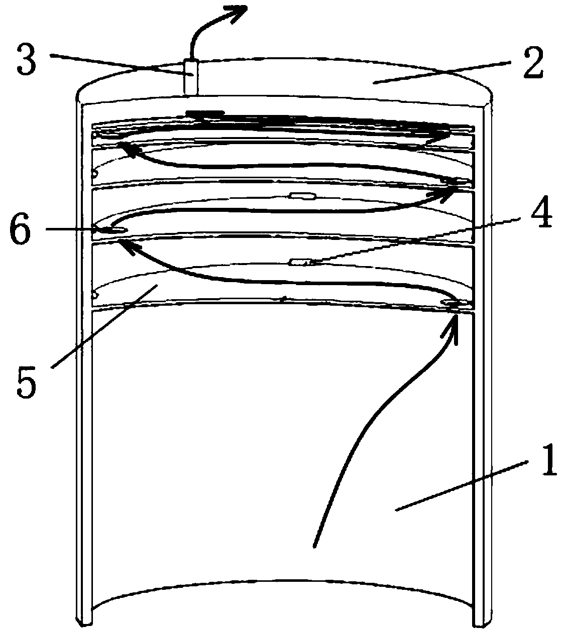
[0031] See the accompanying drawings (the arrows in the figure indicate the flow path of water and air):
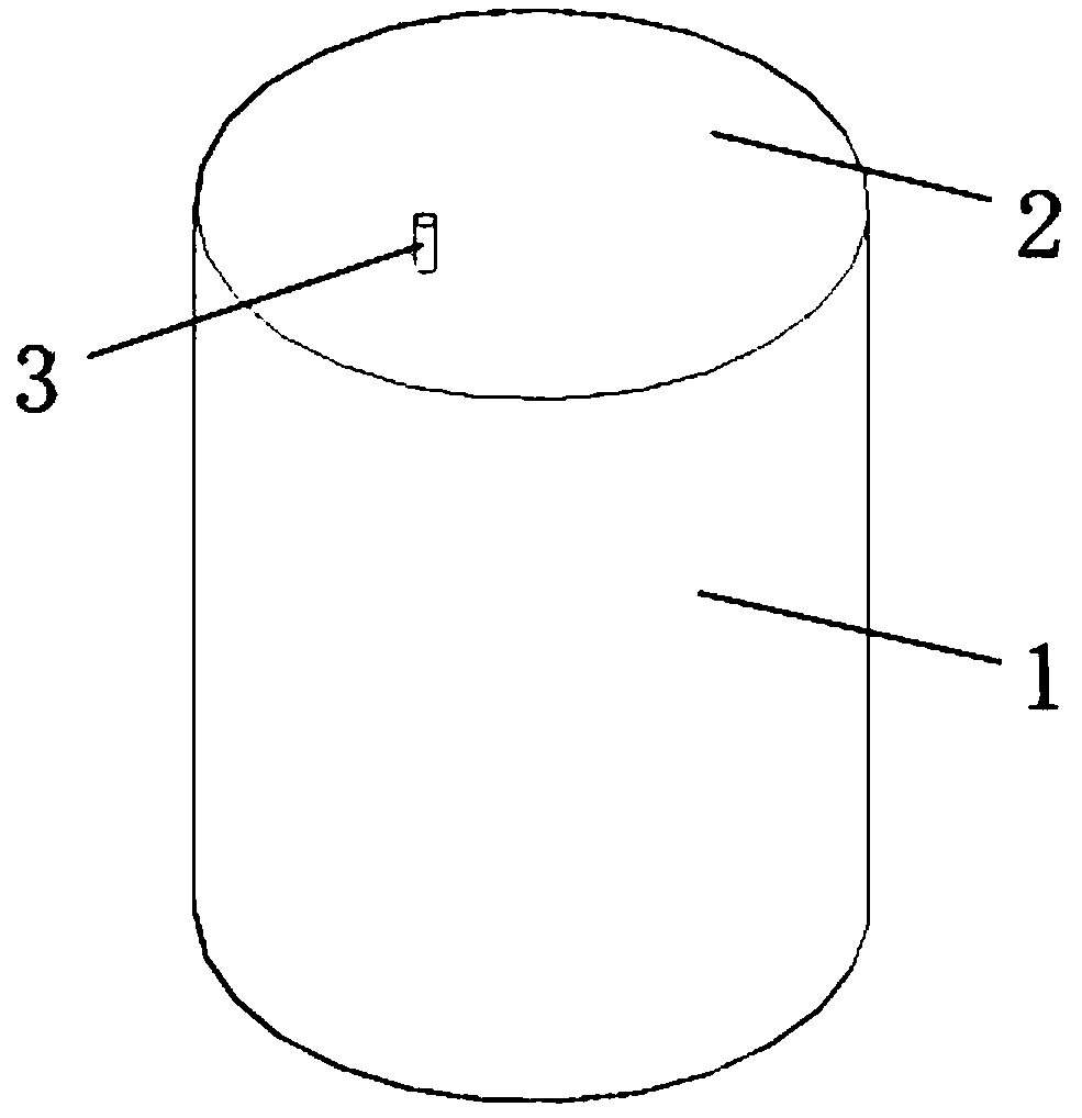
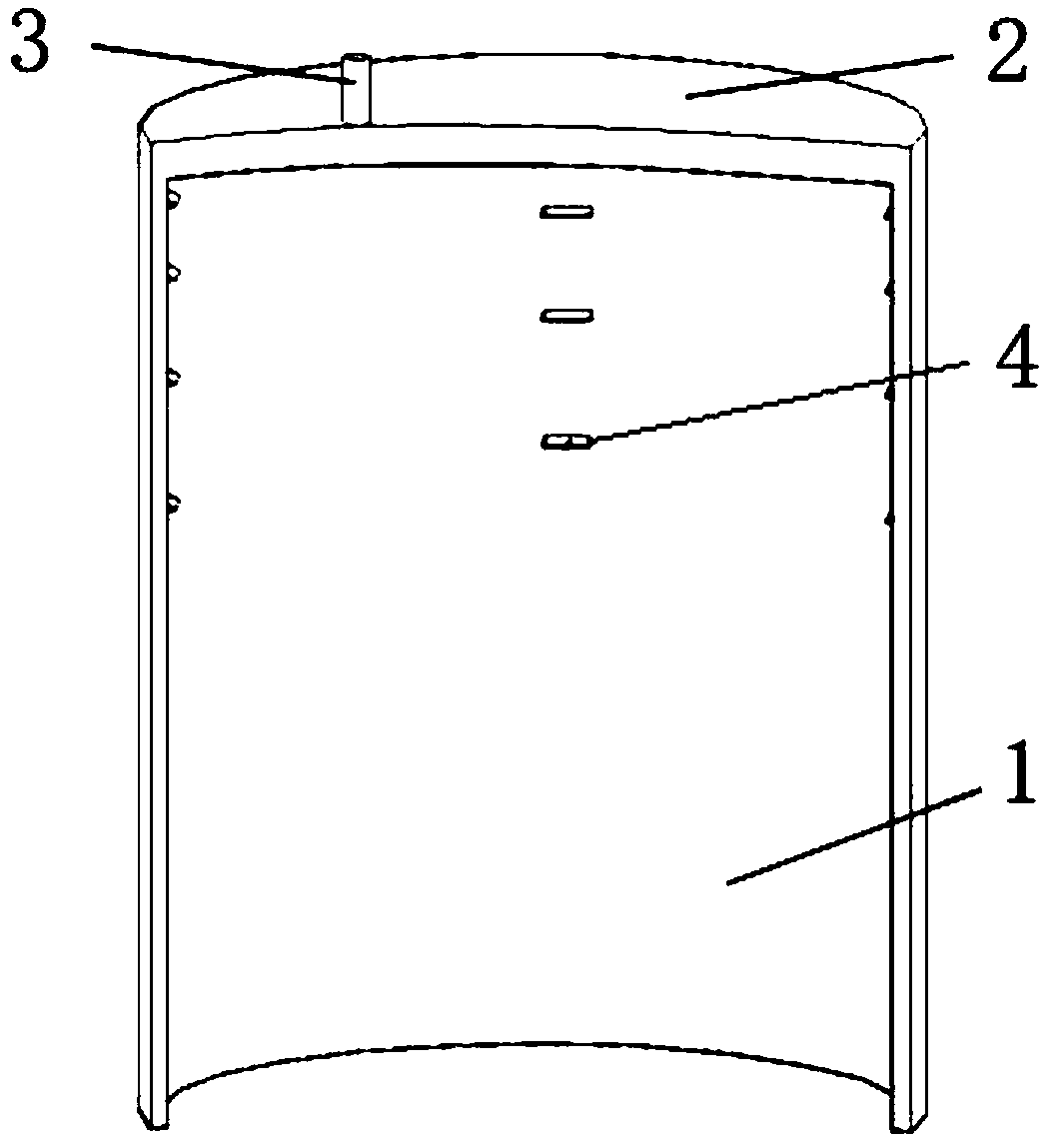
[0032] A bucket-shaped foundation capable of reducing soil plugging, including a cylinder 1, a top plate 2, and a partition 5. The top of the cylinder 1 is sealed and connected with a top plate 2 to form an inverted barrel shape, and the top plate 2 is provided with a water inlet valve 3;
[0033] The inner wall of the cylinder 1 is provided with a plurality of partitions 5 distributed at intervals, and the partitions 5 are in sealing contact with the inner wall of the cylinder 1;
[0034] All partitions 5 are set within 1 / 2 of the cylinder height from the top of the barrel; the spacing between the partitions 5 is not equidistant, and the spacing between adjacent partitions 5 gradually decreases from bottom to top;
[0035] The partitions 5 are made of brittle materials, and each partition 5 is provided with an eccentric reserved hole 6;
[0036] After each dividing plat...
PUM
| Property | Measurement | Unit |
|---|---|---|
| Thickness | aaaaa | aaaaa |
Abstract
Description
Claims
Application Information