Rotor punching and rotor core having same, and motor
A technology of rotor punching and rotor core, which is applied to the rotating parts of the magnetic circuit, the shape/style/structure of the magnetic circuit, etc., can solve the problems of affecting the utilization rate of permanent magnets, the reduction of motor efficiency, and the excess of motor functions. Effects of motor efficiency, reduction of flux leakage, and improvement of utilization
- Summary
- Abstract
- Description
- Claims
- Application Information
AI Technical Summary
Problems solved by technology
Method used
Image

Examples
example 1
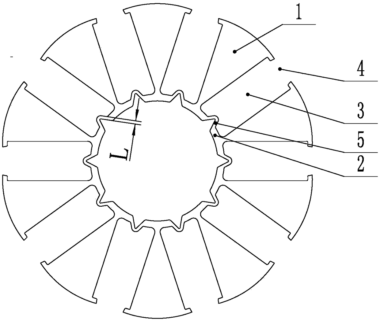
[0030] Such as figure 1 As shown, a rotor punching piece includes a pole portion 1, an inner ring 2, and a magnetic steel groove 3. Two adjacent pole portions 1 form an outer open groove 4 at the outer end of the magnetic steel groove 3; One side of the inner end of each magnetic steel groove 3 is provided with an outwardly protruding magnetic steel stopper 5, and the inner circle side of the stopper 5 is a groove, so that the shape of the stopper 5 is Convex outside and concave inside, its width dimension L satisfies 0.3≤L≤1.5mm.
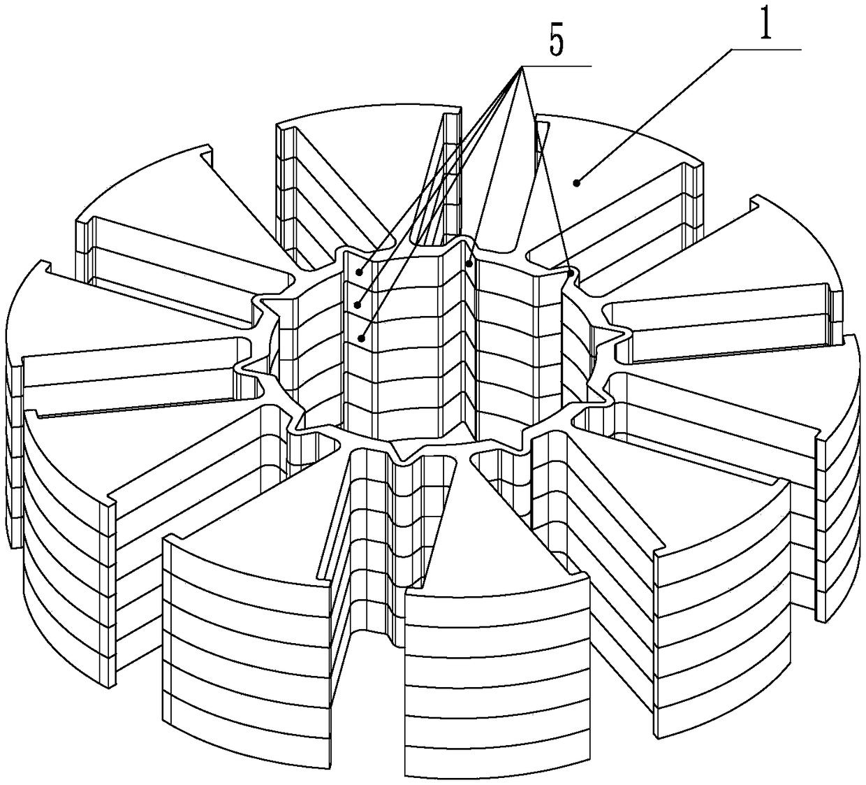
[0031] Such as figure 2 As shown, a rotor core includes a plurality of the above-mentioned rotor punches, and the positioning portions 5 and pole portions 1 of the plurality of rotor punches are aligned up and down, and are laminated along the axial direction.
[0032] A motor whose rotor core adopts the above-mentioned rotor core.
[0033] In this example, the rotor iron core adopts 6 rotor punches, the rotor punches are provided with 10 pole ...
example 2
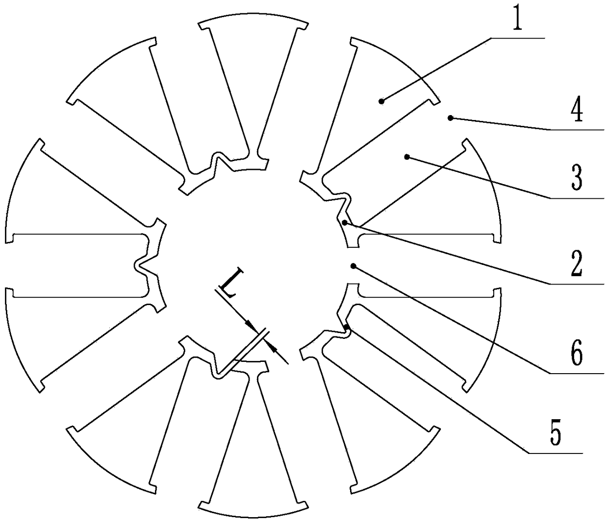
[0035] Such as image 3 As shown, the difference from the above example 1 is that the inner ring 2 is provided with an inner opening groove 6, and the inner opening groove 6 is formed by canceling and disconnecting the limit part 5 at the inner end of the magnetic steel groove 3 at the corresponding position, and the pole part The number of 1 is S, the number of inner open grooves 6 is N, and the number of N satisfies: 0≤N≤S.
[0036] In order to better reduce magnetic flux leakage, the relationship between the number N of inner opening slots 6 and the number S of pole parts 1 satisfies: N is an integer fraction of S, and N is a positive integer. A reasonable number of inner opening slots 6 can better reduce magnetic flux leakage.
[0037] In order to better reduce magnetic flux leakage, the inner opening slots 6 and the limiting parts 5 are arranged alternately along the circumferential direction of the inner ring 2 . The punching structure in which the inner opening slots ...
example 3
[0041] Such as Figure 5 As shown, the difference from the above example 1 or example 2 is that a rotor core includes one or more sets of rotor laminations, each set of rotor laminations includes at least one first rotor lamination 8 and two second rotor laminations. Rotor punching 7, the first rotor punching 8 is the rotor punching of Example 1, the second rotor punching 7 is the rotor punching of Example 2, and the two adjacent second rotor punchings 7 have a rotation angle α, so that the inner opening The grooves 6 and the limiting parts 5 are arranged alternately in the axial direction. This structural shape can effectively balance the mechanical strength of the rotor core and the degree of magnetic flux leakage.
[0042] In this example, the rotor core is composed of two sets of rotor punches. In each set of rotor punches, there is one first rotor punch 8, two second rotor punches 7, and the rotation angle α is 36°.
PUM
 Abstract
Description
Claims
Application Information
 - R&D
- Intellectual Property
- Life Sciences
- Materials
- Tech Scout
- Unparalleled Data Quality
- Higher Quality Content
- 60% Fewer Hallucinations
Browse by: Latest US Patents, China's latest patents, Technical Efficacy Thesaurus, Application Domain, Technology Topic, Popular Technical Reports.
© 2025 PatSnap. All rights reserved.Legal|Privacy policy|Modern Slavery Act Transparency Statement|Sitemap|About US| Contact US: help@patsnap.com