Mop head and mop

A mop head and cleaning technology, applied in the field of mop heads, can solve the problem of insufficient maintenance of cleaning fabrics, etc., and achieve the effects of good use performance and high shape stability

Pending Publication Date: 2019-02-05
CARL FREUDENBERG KG
View PDF12 Cites 0 Cited by
  • Summary
  • Abstract
  • Description
  • Claims
  • Application Information

AI Technical Summary

Problems solved by technology

[0004] But the caveat here is that in normal use of the mop head, e.g. when the cleaning fabric hangs on the corners of the surface being cleaned, especially if cleaning agents are used whic

Method used


Image

  • Mop head and mop
  • Mop head and mop

Examples


Embodiment Construction

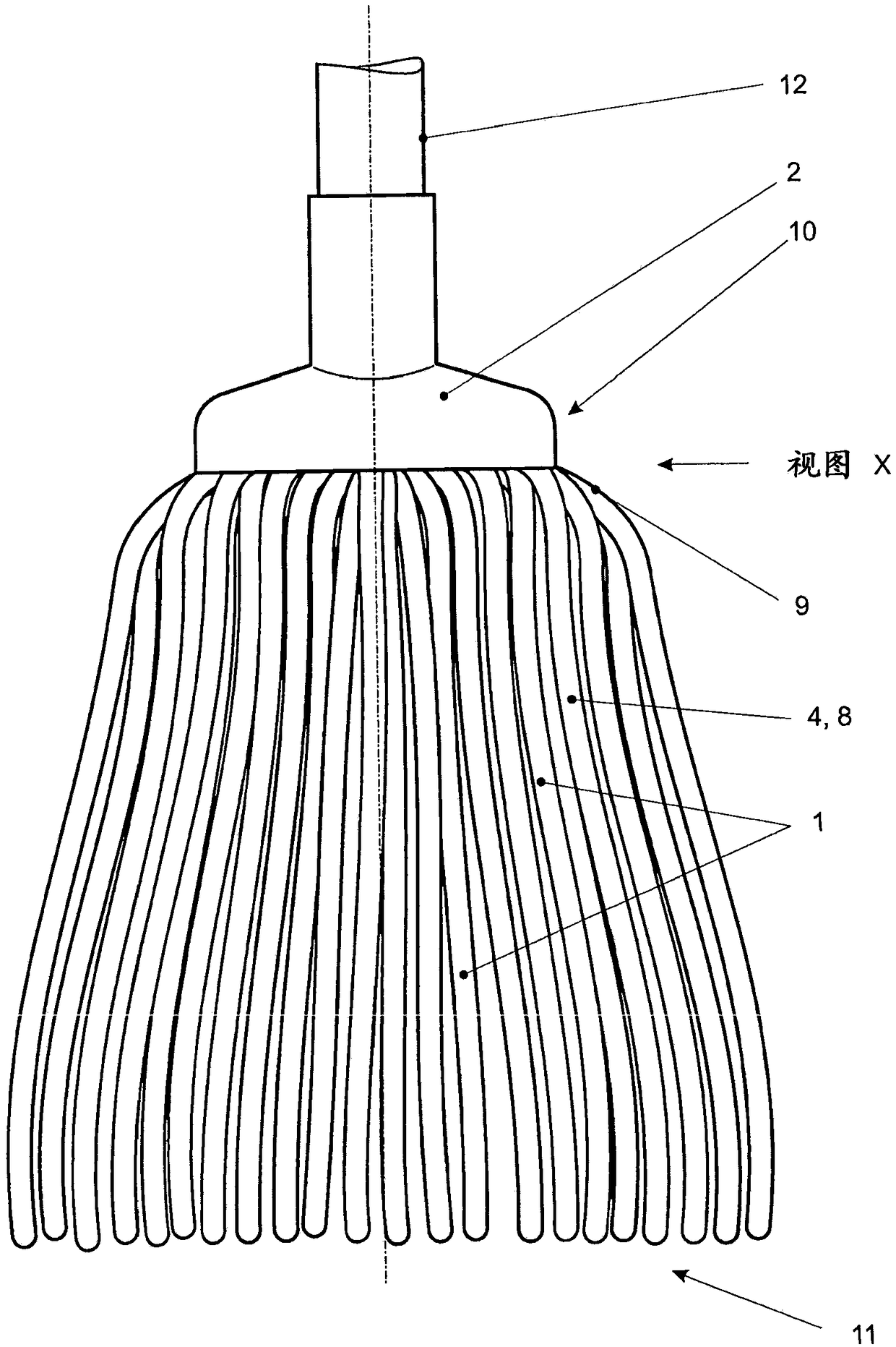
[0026] exist figure 1 An embodiment of a mop according to the invention is shown in . The mop comprises a mop head 11 with its fringe-shaped cleaning fabric 1 and its cap-shaped support body 2 . The cleaning fabric 1 is designed in this exemplary embodiment as a cleaning filament or gauze and is fastened to a carrier made of polymer material.

[0027] The cleaning fabrics 1 are connected to one another by material-bonding connections 3 in the form of ultrasonic welds and combined into a preassembleable unit 4 . The preassembleable unit 4 has a substantially bell-shaped outer shape 8 in the ready-to-use state shown here of the mop head 11 and is held non-positively and / or form-fittingly by means of schematically shown pins 10 on the support body 2.

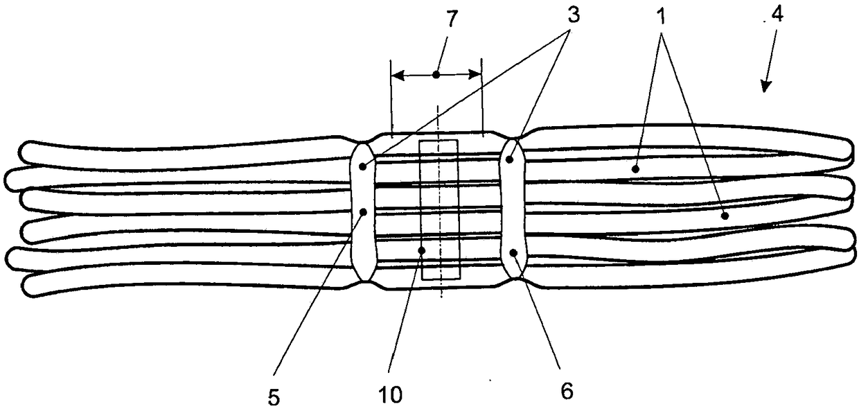
[0028] exist figure 2 A detail of a unit 4 that can be preassembled is shown in . The cleaning fabric 1 is combined with one another by means of a materially bonded connection 3 in the form of an ultrasonic weld to form a pre...


PUM


Abstract

The invention relates to a mop comprising a mop head (11) and a stem (12), said mop head (11) having fringe-shaped cleaning textiles (1) and a cap-shaped carrier body (2), and said cleaning textiles (1) being secured to the carrier body (2). At least some of the cleaning textiles (1) are interconnected by an integral bond (3) and combined to form a pre-assemblable unit (4), said pre-assemblable unit (4) and carrier body (2) being interconnected.

Description

technical field [0001] The invention relates to a mop head comprising a fringe-shaped cleaning fabric and a cap-shaped support body, on which the cleaning fabric is fastened, and to a mop comprising such a mop head. Background technique [0002] Such a mop head and mop are known from EP 1 129 658 A1. [0003] The support body comprises a support plate to which a flexible collar similar to a wire harness can be fastened on the side facing the surface to be cleaned. The fringe-shaped cleaning fabrics are loosely arranged with one another, combined into loose bundles and fastened to the carrier by the flexible loop. The cleaning fabric is clamped between the collar and the carrier plate and is held in its position essentially non-positively. [0004] But the caveat here is that in normal use of the mop head, e.g. when the cleaning fabric hangs on the corners of the surface being cleaned, especially if cleaning agents are used which reduce the static friction between the clean...

Claims


Application Information

Patent Timeline
IPC IPC(8): A47L13/255A47L13/44
CPCA47L13/255A47L13/44A47L13/252A47L13/42
Inventor D·蒂松A·莫雷诺德尔里奥
Owner CARL FREUDENBERG KG
Why Eureka
Try Eureka