
Method for controlling a shock absorber for wheel suspension

A technology of wheel suspension and shock absorber, which is applied in the direction of suspension, elastic suspension, vehicle components, etc., can solve the problem of insufficient accuracy of road surface images, and achieve the effect of improving comfort characteristics

Active Publication Date: 2022-08-09
VOLKSWAGEN AG
View PDF10 Cites 0 Cited by
  • Summary
  • Abstract
  • Description
  • Claims
  • Application Information

AI Technical Summary

Problems solved by technology

[0006] The basic problem when implementing preview functionality based on image data is that the accuracy of road surface images is sometimes insufficient

Method used


Image

  • Method for controlling a shock absorber for wheel suspension
  • Method for controlling a shock absorber for wheel suspension
  • Method for controlling a shock absorber for wheel suspension

Examples


Embodiment Construction

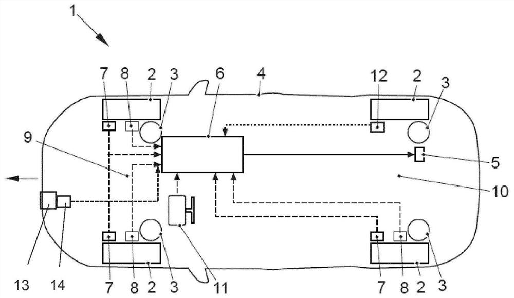
[0029] figure 1 A motor vehicle 1 is shown, the wheel suspension of each wheel 2 of which has a controllable damper 3 via which each wheel 2 supports a vehicle structure 4 . The controllable damper 3 can be embodied as a semi-active or an active damper. exist figure 1 Here, for example, the control valve 5 to which it belongs is indicated for a semi-active damper. The control of the damper 3 with respect to the damping rate is carried out by a control device 6, which can be designed, for example, as described in DE 10 2008 053 ​​007 A1.

[0030] For example, three acceleration sensors 7 are arranged on the vehicle structure 2 . These acceleration sensors may be implemented as vertical acceleration sensors, but are not limited to vertical acceleration sensors. Therefore, from the position of these acceleration sensors on the vehicle structure 2 and the knowledge based on the geometry of the vehicle, the vertical acceleration can be calculated for each point on the vehicle f...


PUM


Abstract

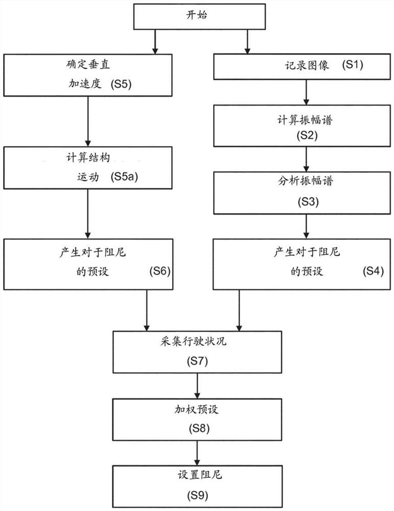
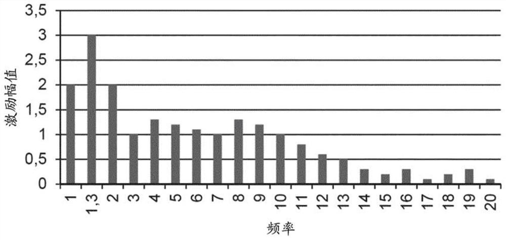
A method for controlling a shock absorber for a wheel suspension of a motor vehicle, comprising generating data (S1) representing the topography of a road surface in front of the motor vehicle, analyzing the data with respect to road surface unevenness, and taking into account the unevenness of the road surface A shock absorber is provided in the case of a flatness analysis, wherein an amplitude spectrum of road unevenness is determined from the data ( S2 , S3 ), and from the amplitude spectrum a preset for the damping of the shock absorber is generated ( S4 ).

Description

technical field [0001] The present invention relates to a method of controlling a shock absorber of a wheel suspension of a motor vehicle, comprising generating data representing the terrain of a road surface in front of the motor vehicle; analyzing the data with respect to road surface unevenness; Set the shock absorber in the case of analysis. Background technique [0002] Unlike passive dampers, controllable dampers can change the damping rate during vehicle driving. For semi-active dampers, the damping force can be influenced by controlling the relief valve. The auxiliary energy used for this purpose is only used here for the valve controller for the purpose of changing the phase of the energy absorption and the energy output by means of the vibration damper. In active vibration dampers, however, auxiliary energy is used to dissipate the desired force with damping in any direction or to induce energy to generate the desired force. Consequently, significantly more ener...

Claims


Application Information

Patent Timeline
Patent Type & Authority Patents(China)
IPC IPC(8): B60G17/08B60G17/0165
CPCB60G17/0165B60G2400/102B60G2400/204B60G2400/821B60G2401/142B60G2500/10B60G17/08
Inventor F.贝雷克K.谢迪S.库克拉
Owner VOLKSWAGEN AG
Learn More