
Umbrella skeleton mechanism, umbrella stand rod and manufacturing method thereof

A technology for umbrella stands and umbrellas, applied in the direction of walking sticks, etc., can solve problems such as low feasibility, complex structure of integral molding mold, and production problem intensity

Pending Publication Date: 2019-02-12
厦门群典家居饰品有限公司
View PDF2 Cites 0 Cited by
  • Summary
  • Abstract
  • Description
  • Claims
  • Application Information

AI Technical Summary

Problems solved by technology

[0004] Such as CN204048402U, since the whole skeleton mechanism is integrally formed, and the first nest and the second nest also have through holes for matching the umbrella pole, so the integrally formed mold needs to be equipped with a core-pulling mechanism, which needs to be equipped with an isolation first bone and The second branch bone and the isolation part that isolates the first nest and the second nest lead to a complex mold structure and a very large space occupation, that is, although the assembly problem is solved, the production problem is actually brought about, and the feasibility is not high;
[0005] Such as CN2423780Y, the parts of the first nest and the second nest are first processed into a belt-shaped structure, and then the belt-shaped structure is surrounded by a sleeve-shaped structure and then locked to maintain the sleeve-shaped structure. On the one hand, adopting this structure will cause the first The structural strength of the first nest and the second nest is reduced. On the other hand, the integrated mold structure is also very complicated and occupies a large space. That is, although the assembly problem is solved, the production problem and the strength problem are actually brought about. Feasibility is not high

Method used


Image

  • Umbrella skeleton mechanism, umbrella stand rod and manufacturing method thereof
  • Umbrella skeleton mechanism, umbrella stand rod and manufacturing method thereof
  • Umbrella skeleton mechanism, umbrella stand rod and manufacturing method thereof

Examples


Embodiment 1

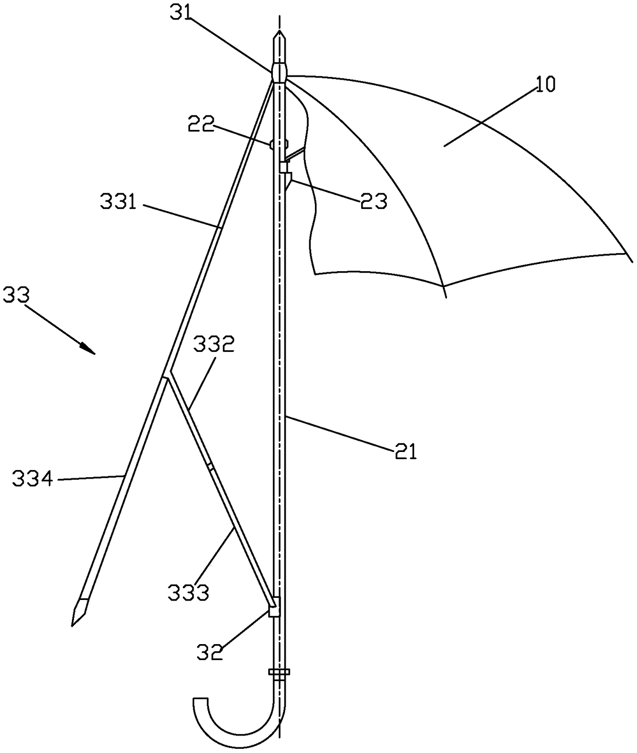
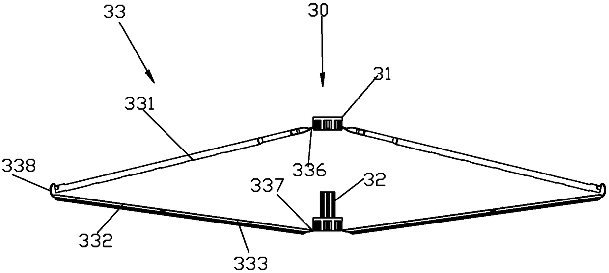
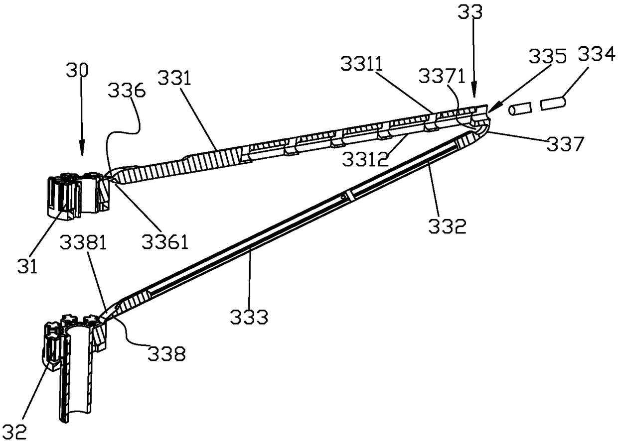
[0051] Please check Figure 1 to Figure 4, the umbrella comprises an umbrella pole and an umbrella cover 10 connected to the umbrella pole, the umbrella pole comprises an umbrella pole 21, a limit pin 22 located on the umbrella pole 21, a positioning device located on the umbrella pole 21 and an umbrella Skeleton mechanism 30 , the positioning device includes an upper jump spring 23 . The umbrella skeleton mechanism 30 includes a first nest 31, a second nest 32 and several skeleton units 33 connected to the first nest 31 and the second nest 32 at evenly spaced intervals in the circumferential direction, and the skeleton unit 33 includes a first rib 331 , the first connecting section 332, the second connecting section 333 and the extension bone 334, the first nest 31, the first ramus 331 and the first connecting section 332 are integrally formed, and the second nest 32 and the second connecting section 333 are also integrated Formed, and between the first nest 31 and the first...

Embodiment 2

[0066] Please check Figure 5 , it is different from Embodiment 1 in that: the second nest 32 and the first nest 31 are arranged up and down relative to the umbrella shaft 21 of the umbrella; the first connecting section 332 is provided with a second insertion part, and the extension bone 324 is fixedly inserted Inside the second insertion part. According to needs, the second connection section 333 can also be provided with a third insertion part, the extension bone 324 passes through the second insertion part and is inserted into the third insertion part, and the first connection section and the second insertion part are fixed through the extension bone. connect segment. The structure of the second insertion part adopts the structure of the first support bone in Embodiment 1, that is, the above-mentioned first groove and the second side wall are respectively provided on the first side wall and the second side wall of the second insertion part. The second groove, the arrange...

Embodiment 3

[0069] It differs from Embodiment 1 in that: Please refer to Figure 6 , the umbrella is a self-opening straight bone umbrella, and the second nest 32 constitutes the middle nest. The skeleton mechanism also includes a lower nest 101, and a pulling bone 102 is connected between the lower nest 101 and the second branch bone.


PUM


Abstract

The invention discloses an umbrella skeleton mechanism, an umbrella stand rod and a manufacturing method thereof. The umbrella skeleton mechanism comprises a first nest, a second nest and a pluralityof skeleton units, and the skeleton units comprise first supporting skeletons; the skeleton units also comprises first connecting sections and second connecting sections, the first nest, the first supporting skeletons and the first connecting sections are integrally formed, the second nest and the second connecting section are also integrally formed, bending parts capable of bending are formed between the first nest and the first supporting skeletons, between the first supporting skeletons and the first connecting sections and between the second nest and the second connecting sections, and thefirst connecting sections and the second connecting sections are fixedly installed together to form the second supporting skeletons or parts of the second supporting skeletons; the umbrella skeletonmechanism can be changed between the folding state and the unfolding state through the bending parts. The umbrella skeleton mechanism has the advantages that the number of the assembling times is decreased, assembling is simplified, the labor cost is reduced, a part production mold structure is simplified, mold occupied space and equipment complexity are reduced, the production cost is reduced, and the strength of parts is improved.

Description

technical field [0001] The invention relates to the technical field of an umbrella stand, in particular to an umbrella skeleton mechanism, an umbrella stand and a manufacturing method thereof. Background technique [0002] The traditional umbrella skeleton mechanism includes a first nest, a second nest and several skeleton units connected to the first nest and the second nest at circumferential intervals. The skeleton unit includes a first branch bone and a second branch bone. One end of a branch is rotatably connected to the first nest through a rotating shaft, one end of the second branch is rotatably connected to the middle of the first branch through a clamp, and the other end of the second branch is connected to the second nest through a rotating shaft. The skeleton mechanism generally has at least four sets of skeleton units according to the needs, and each skeleton unit has three rotating connections that need to be rotated and assembled, which makes the assembly of t...

Claims


Application Information

Patent Timeline
Patent Type & Authority Applications(China)
IPC IPC(8): A45B25/02A45B25/04
CPCA45B25/02A45B25/04
Inventor 陈建宏
Owner 厦门群典家居饰品有限公司
Learn More