
Oscillation device for pharmacy

A technology of oscillation device and adsorption device, which is applied in shaking/vibration/vibration mixer, transportation, packaging, dissolution, etc. It can solve the problems of unusable oscillation device, limited quantity, loss, etc., and achieve the prevention of accidents and the utilization rate of goods High, functional effect

Inactive Publication Date: 2019-02-12
河南精康制药有限公司
View PDF7 Cites 2 Cited by
  • Summary
  • Abstract
  • Description
  • Claims
  • Application Information

AI Technical Summary

Problems solved by technology

[0002] In pharmaceutical experiments, shaking operations are often required, such as shaking samples, mixing solid drugs with liquid drugs, or promoting reactions. Some of the current shaking operations use human hands to shake the test tube directly. This method is not only cumbersome, but also has a poor oscillation effect, and it can only be used for a limited number of test tubes. It cannot be used when a large number of test tubes are used in the experiment. This requires the use of a special oscillation device. Most of the existing oscillation devices It comes with a test tube rack. When in use, place the test tubes that need to be oscillated on the test tube rack of the oscillating device for subsequent operations. However, due to the different sizes of test tubes, the oscillating device cannot be used or needs to be used for different specifications. It is not only cumbersome but also costly to purchase test tubes with different specifications of oscillation devices; there are also some oscillation devices that are provided with a bottom plate on the oscillation motor, and the subsequent oscillation steps are performed by placing the test tube rack on the bottom plate. Second, the fixation of the test tube rack is not enough, which makes the test tube rack easy to fall from the oscillation device during the oscillation process, causing unnecessary losses

Method used


Image

  • Oscillation device for pharmacy
  • Oscillation device for pharmacy
  • Oscillation device for pharmacy

Examples


Embodiment Construction

[0024] The technical solutions of the present invention will be further specifically described below through embodiments and in conjunction with the accompanying drawings.

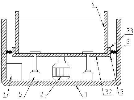
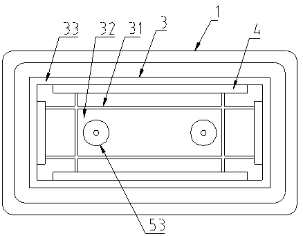
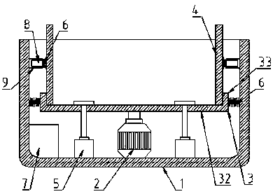
[0025] like figure 1 , figure 2 , image 3 , Figure 4 As shown, a pharmaceutical oscillation device includes a base 1 , a vibration motor 2 , a support plate 3 , a clamping plate 4 and a negative pressure adsorption device 5 .

[0026] Wherein, the inner bottom of the base 1 is provided with a vibrating motor 2, the vibrating motor 2 is provided with a supporting plate 3, the side of the supporting plate 3 is connected to the inner side of the base 1 through a spring 6, and the supporting plate 3 is slidably connected with a clip through a slide rail 31. The holding plate 4 and the supporting plate 3 are also provided with a negative pressure adsorption device 5 , and a control device 7 is provided inside the base 1 to control and connect the vibration motor 2 and the negative pressure adsorption devi...


PUM


Abstract

The invention discloses an oscillation device for pharmacy. The oscillation device comprises a base, a vibration motor, a support plate, a clamping plate and a negative pressure adsorption device, wherein the vibration motor is arranged at the bottom in the base; the support plate is arranged on the vibration motor; the side surface of the support plate is connected with the inside surface of thebase through a spring; the support plate is glidingly connected with the clamping plate through a slide rail; the negative pressure adsorption device is arranged on the support plate; a control deviceis arranged in the base and is used for controlling to connect the vibration motor and the negative pressure adsorption device. The oscillation device has the advantages that the oscillation device is suitable for test tube racks of different sizes, the functionality is stronger, the utilization rate of objects is higher, and the test tube racks in a laboratory can be directly adopted without additional preparation of test tube racks; the test tube racks can be effectively fixed, the firmness is better, and the occurrence of accidents is prevented.

Description

technical field [0001] The invention relates to an oscillating device, in particular to an oscillating device for pharmacy. Background technique [0002] In pharmaceutical experiments, shaking operations are often required, such as shaking samples, mixing solid drugs with liquid drugs, or promoting reactions. Some of the current shaking operations use human hands to shake the test tube directly. This method is not only cumbersome, but also has a poor oscillation effect, and it can only be used for a limited number of test tubes. It cannot be used when a large number of test tubes are used in the experiment. This requires the use of a special oscillation device. Most of the existing oscillation devices It comes with a test tube rack. When in use, place the test tubes that need to be oscillated on the test tube rack of the oscillating device for subsequent operations. However, due to the different sizes of test tubes, the oscillating device cannot be used or needs to be used f...

Claims


Application Information

Patent Timeline
Patent Type & Authority Applications(China)
IPC IPC(8): B01F11/00B01F15/00
CPCB01F31/20B01F31/201B01F35/42B01F2101/22
Inventor 李怀生尼永军武玄之董少华
Owner 河南精康制药有限公司
Learn More