Hydraulic shear

A technology of hydraulic shears and hydraulic cylinders, applied in the field of hydraulic shears, can solve problems such as cutter body damage and reduced efficiency, and achieve the effects of eliminating guide rail gaps, improving shearing quality, and reducing damage

Inactive Publication Date: 2019-02-12
徐广祥
View PDF10 Cites 2 Cited by
  • Summary
  • Abstract
  • Description
  • Claims
  • Application Information

AI Technical Summary

Problems solved by technology

[0004] However, the cutter body on the existing hydraulic shears does not have an effective support body, and it is easy to cause the cutter body to collapse and damage, resulting in a decrease in efficiency. Those skilled in the art hope to provide a tool that can effectively reduce the damage and collapse of the cutter body. Happening

Method used


Image

  • Hydraulic shear
  • Hydraulic shear

Examples


Embodiment 1

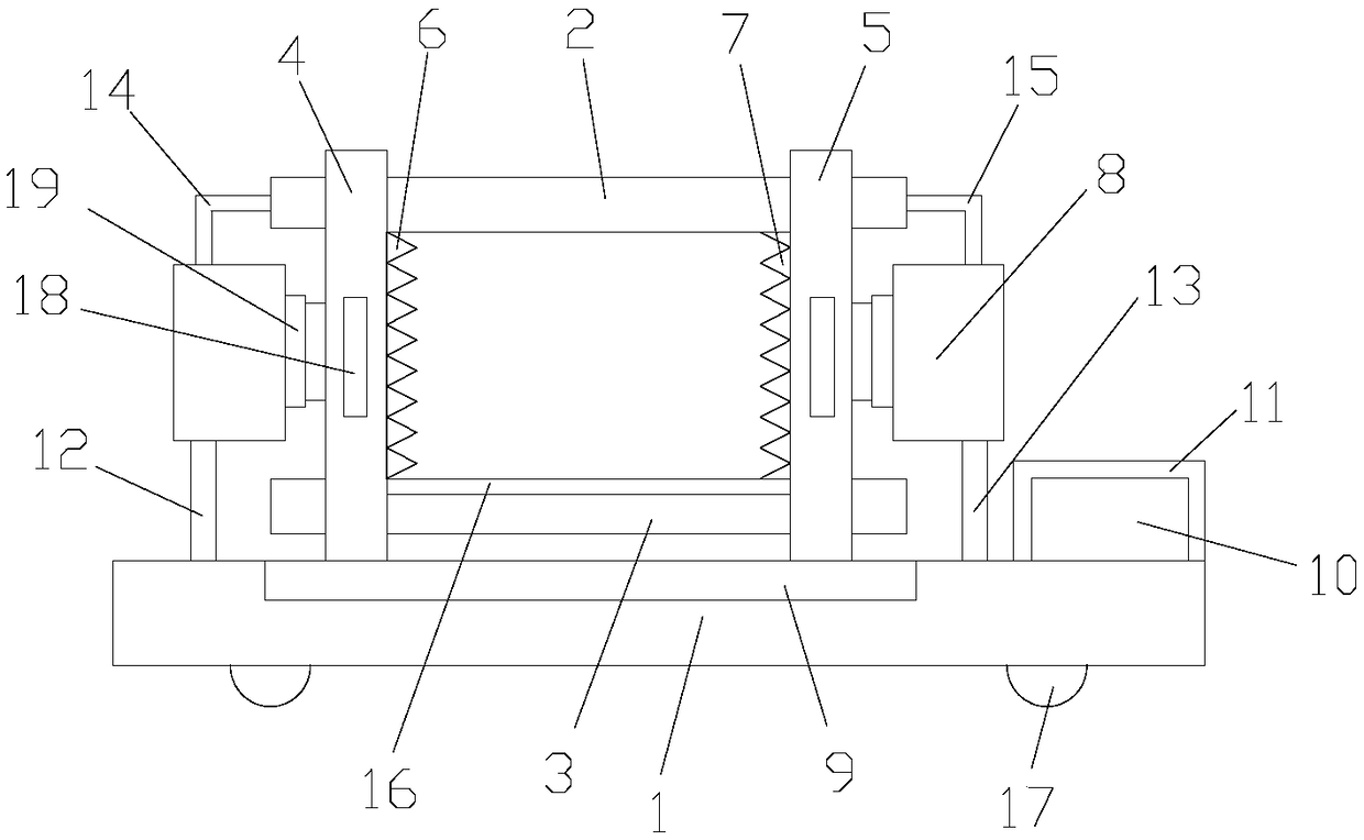
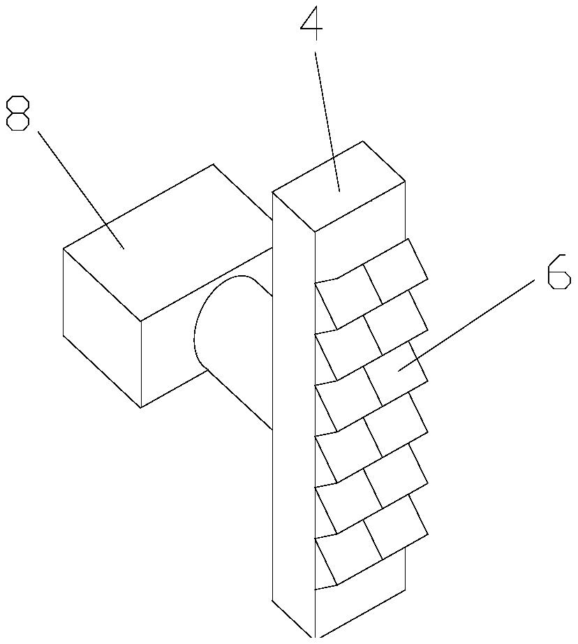
[0024] like figure 1 As shown, a hydraulic shear comprises a base 1 and a hydraulic shear frame positioned above the base, and the hydraulic shear frame includes a first guide post 2, a second guide post 3, a first shear tool holder 4 and a second guide post 4. Two shear blade holders 5, one end of the first guide column 2 and the second guide column 3 all pass through the first shear blade holder 4, and the other ends of the first guide column 2 and the second guide column 3 all pass through The second shearing blade frame 5, the first shearing blade frame 4 and the second shearing blade frame 5 are symmetrically distributed, and the first shearing blade frame 4 and the second shearing blade frame 5 are all connected with the first shearing blade frame 5. A guide column 2 is movably connected with the second guide column 3, the first shearing tool holder 4 is provided with a first cutter body 6, and the second shearing tool holder 5 is provided with a The second cutter body ...

Embodiment 2

[0027] like Figure 1-2 As shown, a hydraulic shear comprises a base 1 and a hydraulic shear frame positioned above the base, and the hydraulic shear frame includes a first guide post 2, a second guide post 3, a first shear tool holder 4 and a second guide post 4. Two shear blade holders 5, one end of the first guide column 2 and the second guide column 3 all pass through the first shear blade holder 4, and the other ends of the first guide column 2 and the second guide column 3 all pass through The second shearing blade frame 5, the first shearing blade frame 4 and the second shearing blade frame 5 are symmetrically distributed, and the first shearing blade frame 4 and the second shearing blade frame 5 are all connected with the first shearing blade frame 5. A guide column 2 is movably connected with the second guide column 3, the first shearing tool holder 4 is provided with a first cutter body 6, and the second shearing tool holder 5 is provided with a The second cutter bo...


PUM


Abstract

The invention discloses a hydraulic shear comprising a base and a hydraulic shear rack located on the base. The hydraulic shear rack comprises a first guiding column, a second guiding column, a firstshearing knife holder and a second shearing knife holder, one end of the first guiding column and one end of the second guiding column penetrate through the first shearing knife holder, the other endof the first guiding column and the other end of the second guiding column penetrate through the second shearing knife holder, the first shearing knife holder and the second shearing knife holder aresymmetrically arranged, the first shearing knife holder and the second shearing knife holder are movably connected to the first guiding column and the second guiding column correspondingly, the firstshearing knife holder is provided with a first knife body, the second shearing knife holder is provided with a second knife body, the first knife body and the second knife body are arranged in a sawtooth shape, the first knife body is detachably connected to the first shearing knife holder, and the second knife body is detachably connected with the second shearing knife holder. The hydraulic shearcan effectively reduce the condition that the knife bodies are damaged.

Description

technical field [0001] The invention relates to a hydraulic shear. Background technique [0002] Powerful hydraulic shears are one of the best demolition and rescue tool products. It adopts the latest design and machining, heat treatment and surface treatment technology, and uses high-strength steel and aviation high-strength aluminum alloy materials. Small, light weight and high quality. [0003] Hydraulic shears are like a big jaw for crushing things, it can bite through metal and other materials used in vehicles. It is characterized by scale display, which is fast, accurate and convenient. [0004] However, the cutter body on the existing hydraulic shears does not have an effective support body, and it is easy to cause the cutter body to collapse and damage, resulting in a decrease in efficiency. Those skilled in the art hope to provide a tool that can effectively reduce the damage and collapse of the cutter body. Happening. Contents of the invention [0005] The te...

Claims


Application Information

Patent Timeline
Patent Type & Authority Applications(China)
IPC IPC(8): B26D1/06B26D5/12B26D7/24A62B3/00
CPCA62B3/00B26D1/06B26D5/12B26D7/24
Inventor 不公告发明人
Owner 徐广祥
Why Eureka
Try Eureka