
Unmanned aerial vehicle clamping device utilizing pressure differential deformation to achieve adhesion stabilization

A clamping device, a technology for drones, which is applied to equipment for loading and unloading goods, aircraft parts, transportation and packaging, etc., can solve frictional heat generation, affect the service life of drones, and speed up the surface cover of drones Aging and damage and other problems, to achieve the effect of eliminating wear and tear

Inactive Publication Date: 2019-02-12
上官小珍
View PDF0 Cites 0 Cited by
  • Summary
  • Abstract
  • Description
  • Claims
  • Application Information

AI Technical Summary

Problems solved by technology

[0004] In view of the deficiencies in the prior art, the purpose of the present invention is to provide a UAV clamping device that utilizes differential pressure deformation and adhesion stability to solve the problem of using a rubber belt to wrap and fix the UAV in the prior art. The drone will shake during transportation, and the rubber belt has good deformation properties, so it can only partially limit the UAV, but cannot keep it fixed, and the UAV will constantly contact with the rubber belt during transportation. Internal friction causes wear on the surface of the drone, and at the same time friction generates heat, which is easy to accelerate the aging and damage of the surface cover of the drone, and affects the service life of the drone.

Method used


Image

  • Unmanned aerial vehicle clamping device utilizing pressure differential deformation to achieve adhesion stabilization
  • Unmanned aerial vehicle clamping device utilizing pressure differential deformation to achieve adhesion stabilization
  • Unmanned aerial vehicle clamping device utilizing pressure differential deformation to achieve adhesion stabilization

Examples


Embodiment Construction

[0028] In order to make the technical means, creative features, goals and effects achieved by the present invention easy to understand, the present invention will be further described below in conjunction with specific embodiments.

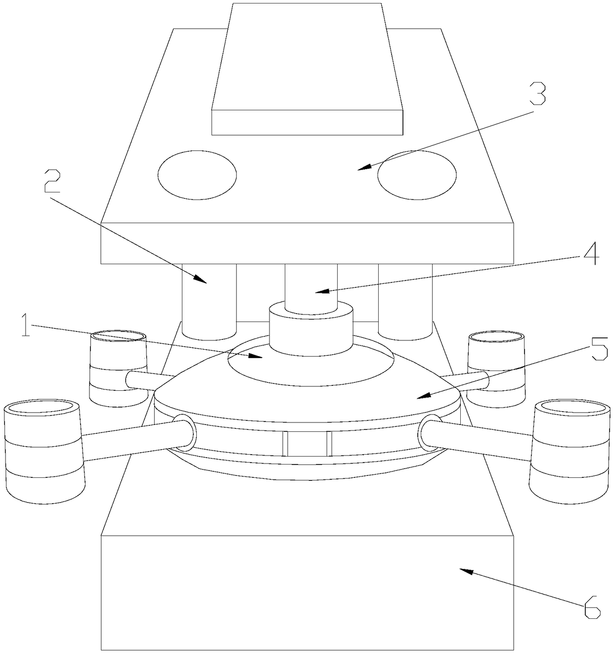
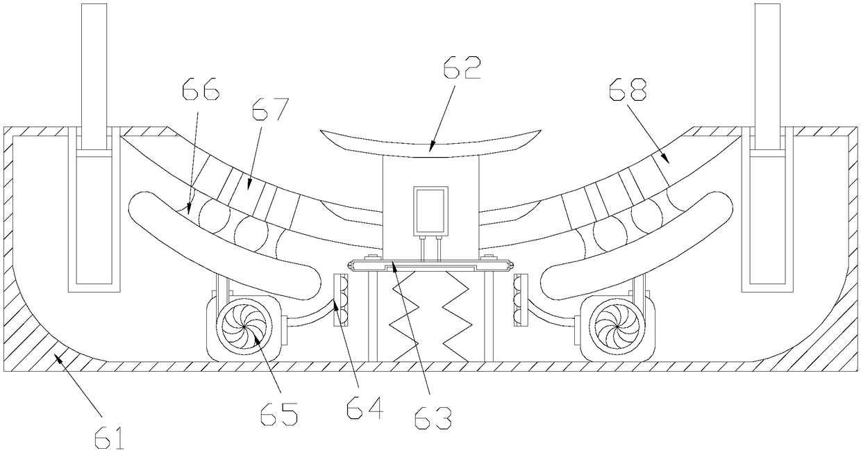
[0029] Such as Figure 1-6 As shown in the figure, the present invention provides a technical solution for a UAV clamping device that utilizes pressure difference deformation adhesion stability:

[0030] Such as Figure 1-2 As shown, a UAV clamping device that utilizes differential pressure deformation and adhesion stability, its structure includes a squeeze plate 1, a support rod 2, a control top plate 3, a telescopic rod 4, a UAV 5, and a fitting anti-wear device 6. The squeeze plate 1 is installed above the drone 5 and connected in a bonded manner. The control top plate 3 is fixedly installed above the anti-wear device 6 through the support rod 2. The control top plate The bottom surface of 3 is embedded with a telescopic rod 4, the bottom en...


PUM


Abstract

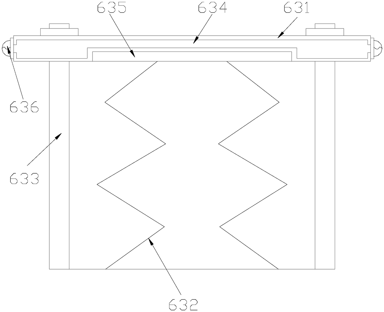
The invention discloses an unmanned aerial vehicle clamping device utilizing pressure differential deformation to achieve adhesion stabilization. The unmanned aerial vehicle clamping device structurally comprises an extrusion disc, supporting rods, a control top plate, a telescopic rod, an unmanned aerial vehicle and an attachment anti-abrasion device. A movable base pushes a sliding plate to drive a conductive groove and a moving contact to downwards move to make contact with a transmitting contact, gas generated by small fans enters a gas cavity and a gas guiding pipe, the flow speed and thepressure of the gas are increased through a hole-shrinkage and pressurization block, thus the gas has enough thrust to push a piston, and the volume of a gas discharge cavity becomes small; and the transmitting contact has a certain height, thus when the movable base downwards moves to a certain distance, the moving contact is disengaged from the transmitting contact, the small fans stop working,meanwhile, the unmanned aerial vehicle is attached to a suction cup, an opening and closing valve is closed, the piston loses pushing force and then is slightly reset, thus the volume of the gas discharge cavity becomes large, the interior of the gas discharge cavity and a conducting pipe are both in a low-pressure sate, thus the suction and the bottom face of the unmanned aerial vehicle are completely sucked for fixing, and the surface of the unmanned aerial vehicle is prevented from being abraded.

Description

technical field [0001] The invention relates to the field of clamping and fixing of unmanned aerial vehicle, more precisely, it is a clamping device for unmanned aerial vehicle that utilizes pressure difference, deformation, adhesion and stability. Background technique [0002] With the advancement and development of science and technology, drones are used more frequently because they have good reconnaissance capabilities, can provide comprehensive information, and are convenient and safe to operate. When drones are not in use, most of them are Fixing the UAV by wrapping the outer side of the UAV with a rubber band, the existing traditional technology is not comprehensive, and has the following disadvantages: [0003] Use a rubber belt to wrap and fix the UAV. Since the UAV will shake during transportation, and the rubber belt has good deformation properties, it can only partially limit the UAV and cannot fix it. During the transportation process, the UAV will constantly ru...

Claims


Application Information

Patent Timeline
Patent Type & Authority Applications(China)
IPC IPC(8): B64D9/00
CPCB64D9/00
Inventor 上官小珍
Owner 上官小珍
Learn More