
Box opening separating plate machine

The technology of a separator and unpacking machine, which is applied in packaging and other directions, can solve the problems of increasing the difficulty of grabbing or clamping the packaging box, the difficult vertical state of the packaging box, and delaying the upgrading speed of large-scale consumer packaging technology.

Active Publication Date: 2019-02-12
苏州澳昆智能机器人技术有限公司
View PDF10 Cites 1 Cited by
  • Summary
  • Abstract
  • Description
  • Claims
  • Application Information

AI Technical Summary

Problems solved by technology

[0002] In the field of large-scale consumer goods packaging technology, when the packaging box is ready for packaging, it is mostly placed in a horizontally placed storage tank, and the conveyor belt in the storage tank can drive the packaging box to travel for the gripper to grab or Clamping and unpacking, due to the influence of gravity on the packaging box itself, it is difficult to maintain the vertical state of the packaging box, so that the grabbing or clamping tools need to adapt to the inclination angle of the packaging box; when the packaging box is forced to maintain a vertical state , It also increases the difficulty of grabbing or clamping the packaging box, so it brings certain troubles to the design, production and packaging process. Due to the packaging of large-scale consumer goods, the pursuit of factors such as scale, speed, and efficiency leads to the above-mentioned The problem is further magnified, thus delaying the upgrading of large-scale consumer product packaging technology; at the same time, since the smiley face bag is a newly developed dairy product, the shape of the milk bag of the milk product is very different, so the packaging used for the milk product The packing box, side partitions, lower partitions and other linings need to be redesigned

Method used


Image

  • Box opening separating plate machine
  • Box opening separating plate machine
  • Box opening separating plate machine

Examples


Embodiment Construction

[0087]The present invention will be further described below in conjunction with the accompanying drawings and embodiments.

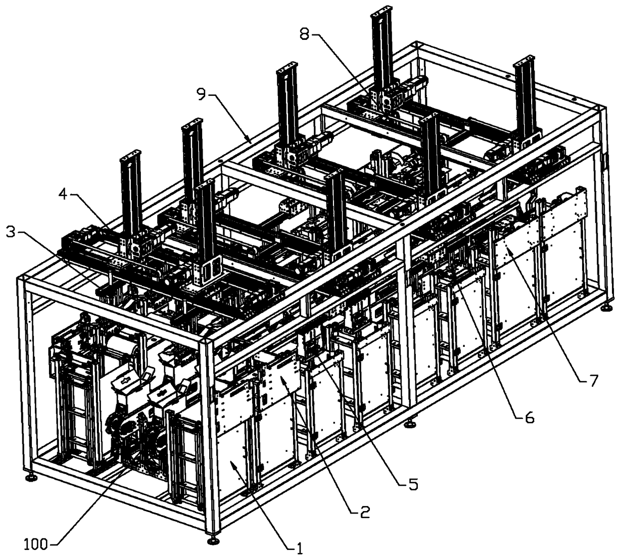
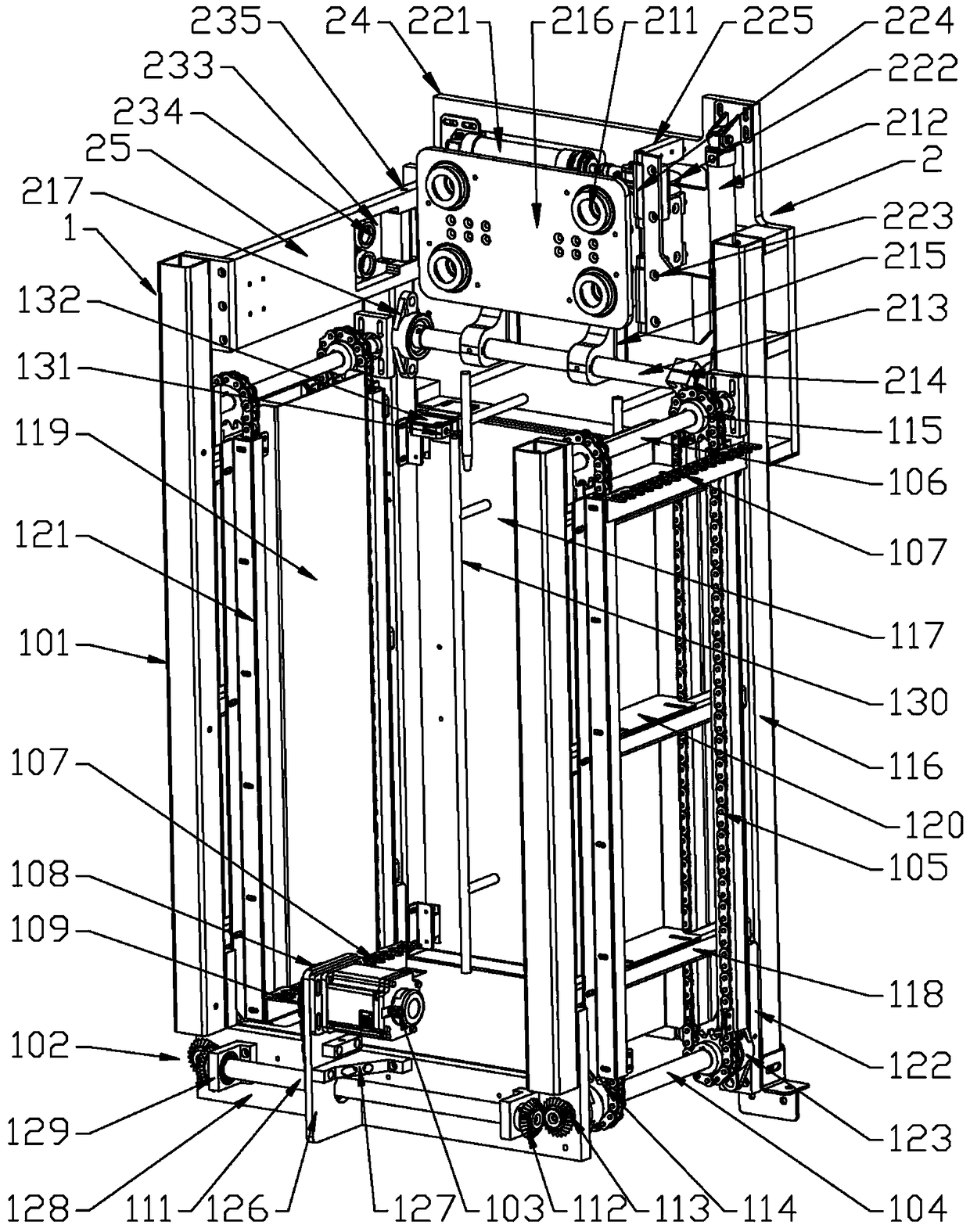
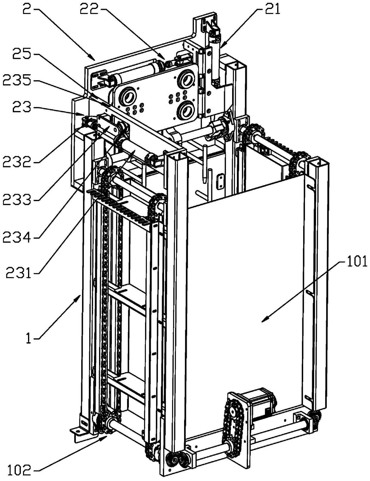
[0088] Such as figure 1 Shown: a kind of unpacking bulkhead machine, comprises unpacking bulkhead frame 9 and packing box conveying line 100, in the unpacking bulkhead frame 9 and along the running direction of packing box conveying line 100, be provided with including Three stations of unpacking station, lower partition station, and side partition station, or four stations including unpacking station, lower partition station, gasket station, and side partition station; the above-mentioned The stations are all correspondingly provided with a material storage feeder 1 fixed on the chassis of the unpacking partition frame 9 and a conveying module 4 fixed on the top of the unpacking partition frame 9, and the storage material at the unpacking station The top of the feeder 1 is equipped with a case unpacking machine 2 and the bottom of the conveying module ...


PUM


Abstract

The invention discloses a box opening separating plate machine. The box opening separating plate machine comprises a box opening separating plate machine frame (9), and there stations including the box opening station, the lower separating plate station and the side separating plate station or four stations including the box opening station, the lower separating plate station, the gasket station and the side separating plate station are sequentially arranged in the box opening separating plate machine frame (9) in the running direction of a package box conveying line (100); the above stationsare correspondingly provided with a storage feeder (1) fixed to a chassis of the box opening separating plate machine frame (9) and a conveying module (4) fixed to the top of the box opening separating plate machine frame (9); and a box opening machine (2) and a box supporting clamping apparatus (3) are further arranged at the box opening station, a lower separating clamping apparatus (5) is arranged at the lower separating plate station, a gasket clamping apparatus (6) is arranged at the gasket station, and a side separating plate forming mechanism (7) and a side separating plate clamping apparatus (8) are arranged at the side separating plate station. The box opening separating plate machine is specially designed for smiley bags and milk bags, the structure is simple, the box opening separating plate machine is precise and high in efficiency.

Description

technical field [0001] The present invention relates to the technical field of packaging of large-scale consumer goods, and in particular to storage feeding, forming, grabbing and conveying technology for packaging boxes, lower partitions, side partitions or packaging boxes, lower partitions, gaskets and side partitions Specifically, it is an unpacking partition that places the material horizontally in the storage tank, feeds the material vertically upwards, and places the formed material on the packing box conveying line through the corresponding jig and conveying module after forming machine. Background technique [0002] In the field of large-scale consumer goods packaging technology, when the packaging box is ready for packaging, it is mostly placed in a horizontally placed storage tank, and the conveyor belt in the storage tank can drive the packaging box to travel for the gripper to grab or Clamping and unpacking, due to the influence of gravity on the packaging box i...

Claims


Application Information

Patent Timeline
IPC IPC(8): B65B43/18B65B43/26B65B61/20
CPCB65B43/18B65B43/265B65B61/20
Inventor 李政德刘霞
Owner 苏州澳昆智能机器人技术有限公司
Learn More