
High-speed plate placing machine for PCB production

A high-speed technology of plate placement machine, used in conveyors, conveyor objects, destacking of objects, etc., can solve the problems of slow plate placement, error-prone, and increased labor costs.

Pending Publication Date: 2019-02-12
AOSHIKANG TECH CO LTD
View PDF0 Cites 15 Cited by
  • Summary
  • Abstract
  • Description
  • Claims
  • Application Information

AI Technical Summary

Problems solved by technology

[0003] However, the traditional method of placing the board manually increases the labor cost, and at the same time, the speed of placing the board is slow and error-prone

Method used


Image

  • High-speed plate placing machine for PCB production
  • High-speed plate placing machine for PCB production
  • High-speed plate placing machine for PCB production

Examples


Embodiment

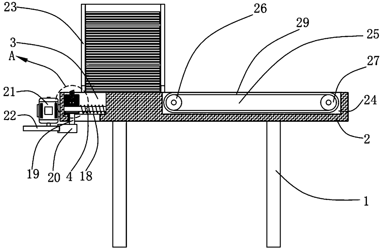
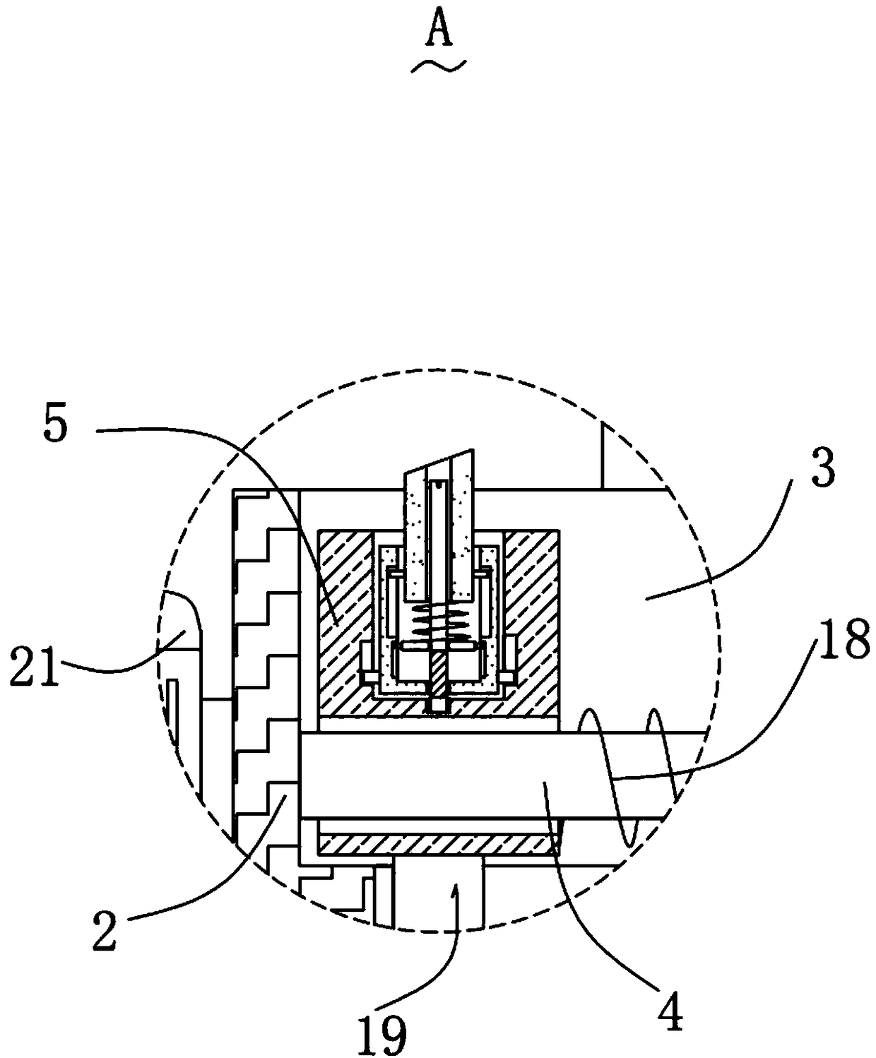
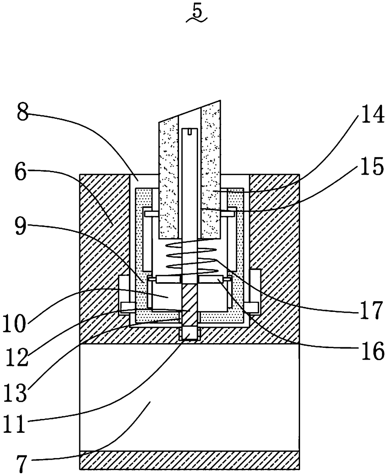
[0026] Please refer to figure 1 , figure 2 , image 3 , Figure 4 with Figure 5 ,in, figure 1 A schematic structural view of a preferred embodiment of the high-speed board machine for PCB production provided by the present invention; figure 2 for figure 1 The schematic diagram of the enlarged structure of part A shown; image 3 for figure 1 Structural schematic diagram of the push structure shown; Figure 4 for figure 1 The schematic diagram of the side view structure is shown; Figure 5 for figure 1 The schematic diagram of the three-dimensional structure of the cam shown. The high-speed board release machine for PCB production includes: two support plates 1; a mounting plate 2, which is fixedly installed on the top of the two support plates 1; a first sliding groove 3, the first sliding groove 3 Set on the top of the mounting plate 2; a crossbar 4, the crossbar 4 is fixedly installed in the first sliding groove 3; a pushing structure 5, the pushing structure 5...


PUM


Abstract

The invention provides a high-speed plate placing machine for PCB production. The high-speed plate placing machine for the PCB production comprises two supporting plates, a mounting plate, a first sliding groove, a cross rod, a pushing structure, a first spring and a supporting rod, wherein the mounting plate is fixedly installed at the tops of the two supporting plates, the first sliding groove is formed in the top of the mounting plate, the cross rod is fixedly installed in the first sliding groove, the pushing structure is installed on the cross rod in a sliding mode, the first spring is arranged on the outer side of the cross rod in a sliding mode, one end of the first spring is fixedly connected with the inner wall of the first sliding groove, the supporting rod is fixedly installed at the bottom of the pushing structure, and the bottom end of the supporting rod extends out of the first sliding groove. The high-speed plate placing machine for the PCB production has the advantagesof being convenient to use, the PCB with different thicknesses can be placed, the plate placing speed is high, and mistakes are not prone to being caused.

Description

technical field [0001] The invention relates to the technical field of PCB production, in particular to a high-speed board placement machine for PCB production. Background technique [0002] The Chinese name of PCB is printed circuit board, also known as printed circuit board. It is an important electronic component, a support for electronic components, and a carrier for electrical connections of electronic components. Because it is made by electronic printing, it is Known as a "printed" circuit board, during the PCB production process, the PCB board needs to be placed on the production line. [0003] However, the traditional way of placing boards manually increases labor costs, and at the same time, the speed of board placement is slow and error-prone. [0004] Therefore, it is necessary to provide a new PCB production high-speed board machine to solve the above technical problems. Contents of the invention [0005] The technical problem to be solved by the present inve...

Claims


Application Information

Patent Timeline
Patent Type & Authority Applications(China)
IPC IPC(8): B65G47/82B65G59/06
CPCB65G47/82B65G59/067B65G2201/022
Inventor 陈志新吴玉海李想宋波
Owner AOSHIKANG TECH CO LTD
Learn More