Eureka AIR delivers breakthrough ideas for toughest innovation challenges, trusted by R&D personnel around the world.

Screen automatic splicing method and screen automatic splicing system

An automatic splicing and screen splicing technology, applied in the transmission system, near-field transmission system, electrical components, etc., can solve the problems of inconvenient maintenance, cumbersome process, and time-consuming manual configuration, and achieve difficult and high-cost production. Effect

Pending Publication Date: 2019-02-12
APPOTRONICS CORP LTD
View PDF2 Cites 1 Cited by
  • Summary
  • Abstract
  • Description
  • Claims
  • Application Information

AI Technical Summary

Problems solved by technology

[0003] However, in the current multi-screen splicing system on the market, each screen and its supporting equipment are manually positioned and configured, which is cumbersome and inconvenient to maintain
For example, when the number of screens to be spliced ​​is large, manual configuration takes a long time and is prone to configuration errors
In addition, if a certain screen fails during use and needs to be repaired or replaced, the entire system needs to be reconfigured

Method used


Image

  • Screen automatic splicing method and screen automatic splicing system
  • Screen automatic splicing method and screen automatic splicing system
  • Screen automatic splicing method and screen automatic splicing system

Examples


Embodiment Construction

[0030] Hereinafter, specific embodiments according to the present invention will be described in detail with reference to the accompanying drawings. It should be emphasized that the drawings are only schematic and not necessarily true to scale, and thus are not limiting.

[0031] 1. Overview of automatic screen splicing system and automatic screen splicing method

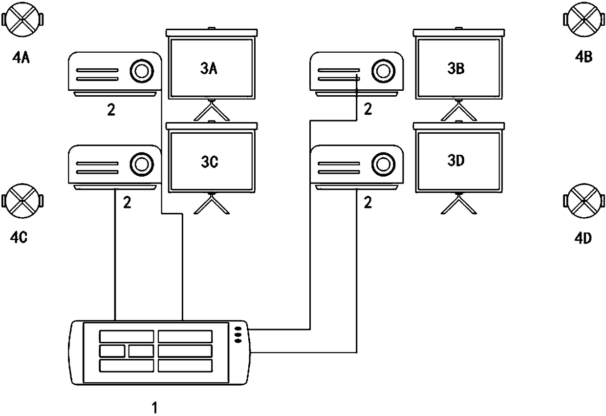
[0032] figure 1 A schematic diagram of a screen splicing system according to an embodiment of the present invention is shown. The system is mainly used in application environments that require super-large video display, such as advertising walls, monitoring centers, dispatch centers, conference rooms, and exhibition halls. Such as figure 1 As shown, the screen splicing system includes a video signal source (not shown), a video distributor 1, a projector 2, a projection screen 3, a wireless communication slave device 4 and a wireless communication master device 5 (see Figure 5 ~ Figure 7 ). Projection screens 3...


PUM


Abstract

The invention discloses a screen automatic splicing system comprising a plurality of screens and a screen automatic splicing method for the system. The plurality of screens are provided with a wireless communication master device, and the periphery of the plurality of screens is provided with a plurality of wireless communication slave devices. The method comprises the following steps: a wirelesscommunication master device on each screen initiates scanning, identifies and receives signals from each wireless communication slave device; Calculating a distance from each of the screens to each ofthe wireless communication slave devices according to ranging information of the signals received by each of the wireless communication master devices; Obtaining coordinates of each of the screens ina plane coordinate system according to the distance, and completing automatic positioning of each of the screens; Dividing a video image into sub-video images corresponding to each of the screens according to the coordinates of each of the screens and distributing the sub-video images; Each of the screens displays the corresponding sub-video images, and each of the sub-video images is stitched toform the video image.

Description

technical field [0001] The invention relates to the field of video splicing processing. Specifically, the present invention relates to an automatic screen splicing method using wireless communication positioning technology and an automatic screen splicing system using the method. Background technique [0002] In recent years, with the development of the national economy and the advancement of science and technology, people's demand for super-large video display equipment continues to grow. Due to the difficulty and high cost of producing large-size single-screen TVs, multiple screen splicing methods are generally used to meet people's needs for super-large-screen video display. The multi-screen splicing system commonly used in the market currently divides the video image into multiple partial images, and each partial image is displayed on a different screen in a predetermined order, thereby realizing super-large-screen display. [0003] However, in the current multi-screen...

Claims


Application Information

Patent Timeline
Patent Type & Authority Applications(China)
IPC IPC(8): G06F3/14H04B5/00
CPCG06F3/14H04B5/70H04B5/00
Inventor 鄢圣巍李屹
Owner APPOTRONICS CORP LTD
Why Eureka
Eureka Blog
Learn More