Auxiliary clamp for two-sided flexible circuit board printing correction
What is Al technical title?
Al technical title is built by PatSnap Al team. It summarizes the technical point description of the patent document.
A technology for flexible circuit boards and auxiliary fixtures, applied in printed circuits, printed circuit manufacturing, electrical components, etc., can solve problems such as easy to fall off, low reliability in use, poor clamping effect of flexible circuit boards, etc., to improve the clamping effect , Improve the reliability of use and improve the quality of printing operations
Inactive Publication Date: 2019-02-12
YANCHENG HUAYU PHOTOELECTRIC TECH CO LTD
View PDF0 Cites 5 Cited by
Summary
Abstract
Description
Claims
Application Information
AI Technical Summary
This helps you quickly interpret patents by identifying the three key elements:
Problems solved by technology
Method used
Benefits of technology
Problems solved by technology
[0002] As we all know, a flexible circuit board is a printed circuit board supported by a flexible insulating substrate such as polyimide or polyester film. It has high reliability, excellent flexibility, and can be greatly bent. At the same time, it also has the characteristics of high wiring density, light weight, thin thickness, and good bendability. The double-sided flexible circuit board printing correction auxiliary fixture is a kind of flexible circuit board used in the process of double-sided printing. , for correction and clamping, in order to better complete the auxiliary device of double-sided printing, which has been widely used in the field of flexible circuit board printing correction; the existing double-sided flexible circuit board printing correction auxiliary fixture includes printing Board, four sets of legs, left clamping mechanism and right clamping mechanism, the tops of the four sets of legs are connected with the left front side, left rear side, right front side and right rear side of the bottom end of the printed board, and the left clamping mechanism and the right The bottom of the clamping mechanism is respectively connected to the left and right sides of the top of the printed board; when using the existing double-sided flexible circuit board printing correction auxiliary fixture, firstly, the flexible circuit board is clamped by the left clamping mechanism and the right clamping mechanism. Tighten, and then print on the front of the flexible circuit board. After the printing is completed, open the left clamping mechanism and the right clamping mechanism, turn the flexible circuit board over and continue clamping, and then perform the same process printing on the reverse side; the existing During the use of the double-sided flexible circuit board printing and correction auxiliary fixture, it was found that the clamping effect of the left clamping mechanism and the right clamping mechanism on the flexible circuit board is poor, and it is often easy to fall off, and the reliability of use is low; at the same time, it needs to be manually disassembled. Flip, cannot be flipped directly, which will easily damage the printed area during the flip process, the printing yield is low, and the practicability is poor; and during the clamping process of the flexible circuit board, due to the softness of the flexible circuit board, often occur Slack, unable to adjust flattening, affecting printing operations, resulting in high limitations in use
Method used
Image
Click on the blue label to locate the original text in one second.
Reading with bidirectional positioning of images and text.
Examples
Embodiment Construction
[0015] The specific implementation manners of the present invention will be further described in detail below in conjunction with the accompanying drawings and embodiments. The following examples are used to illustrate the present invention, but are not intended to limit the scope of the present invention.
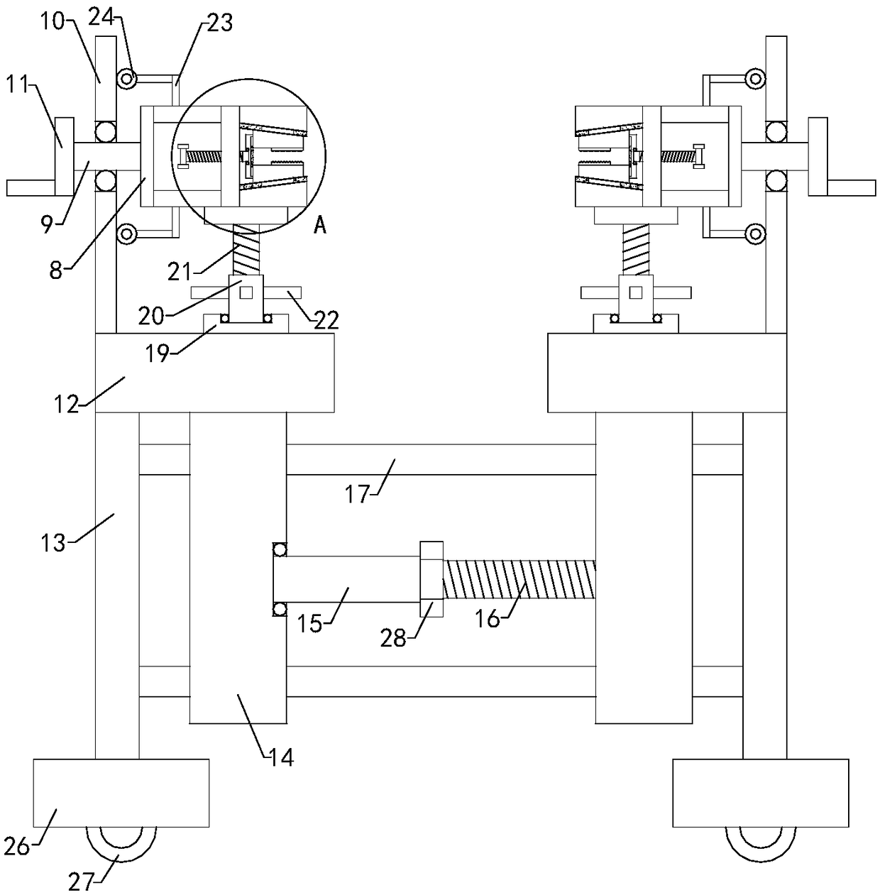
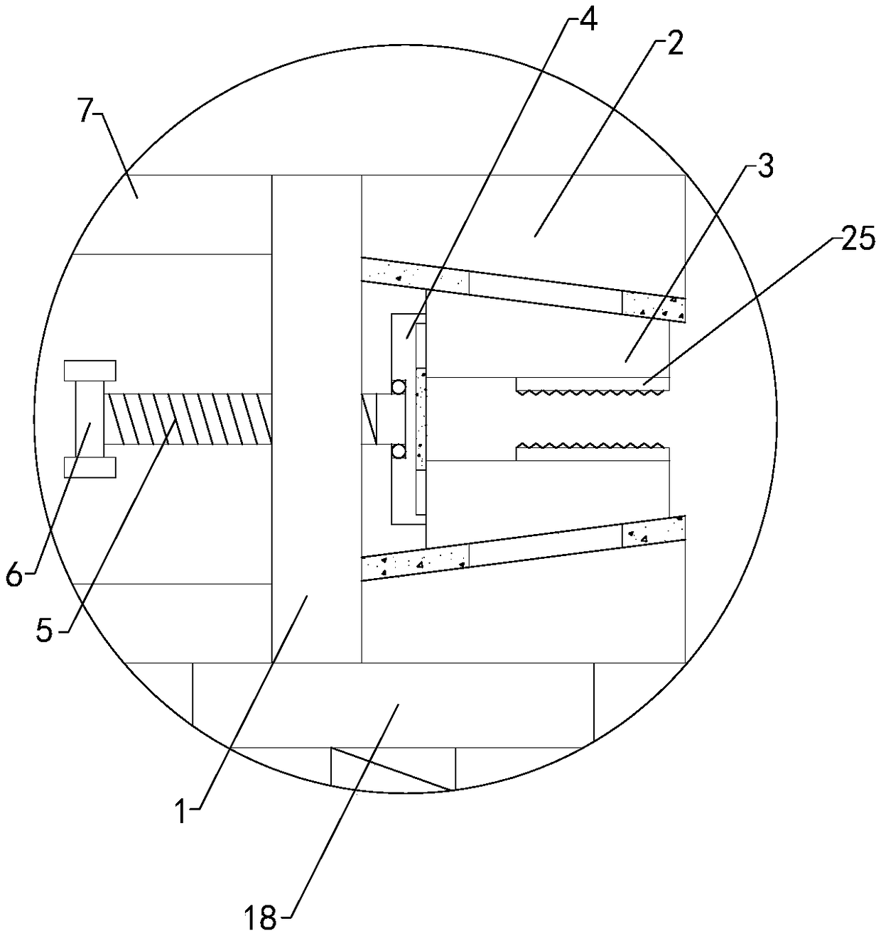
[0016] Such as Figure 1 to Figure 2 As shown, a double-sided flexible circuit board printing correction auxiliary fixture of the present invention includes a left fixing plate 1, a left upper clamping plate 2, a left lower clamping plate, a left upper clamping plate 3, a left lower clamping plate, a left push plate 4, and a left adjusting screw 5 , left knob 6, right fixing plate, right upper clamping plate, right lower clamping plate, right upper clamping plate, right lower clamping plate, right push plate, right adjusting screw and right knob, the left ends of left upper clamping plate and left lower clamping plate are respectively fixed with the left The upper side a...
PUM
Abstract
The invention relates to the technical field of two-sided flexible circuit board accessory devices, in particular to an auxiliary clamp for two-sided flexible circuit board printing correction. The auxiliary clamp comprises a left fixing plate, a left upper retaining plate, a left lower retaining plate, a left upper clamping plate, a left lower clamping plate, a left push plate, a left adjusting screw rod, a left knob, a right fixing plate, a right upper retaining plate, a right lower retaining plate, a right upper clamping plate, a right lower clamping plate, a right push plate, a right adjusting screw rod, a right knob, a left upper side plate, a left blocking plate, a left lower side plate, a left rotating shaft, a left supporting plate, a left hand wheel, a right upper side plate, a right blocking plate, a right lower side plate, a right rotating shaft, a right supporting plate, a right hand wheel, a left placement plate, a right placement plate, a left supporting plate, a right supporting plate, a left adjusting block, a right adjusting block, a first threaded pipe, a first threaded rod, an upper connection slide column and a lower connection slide column. The auxiliary clamphas advantages that clamping effects can be improved, and reliability in use is improved; practicality is improved due to availability for direct turning; due to expansion adjustment, printing qualityis improved, and limitation in use is lowered.
Description
technical field [0001] The invention relates to the technical field of double-sided flexible circuit board attachments, in particular to an auxiliary jig for printing and correcting double-sided flexible circuit boards. Background technique [0002] As we all know, a flexible circuit board is a printed circuit board supported by a flexible insulating substrate such as polyimide or polyester film. It has high reliability, excellent flexibility, and can be greatly bent. At the same time, it also has the characteristics of high wiring density, light weight, thin thickness, and good bendability. The double-sided flexible circuit board printing correction auxiliary fixture is a kind of flexible circuit board used in the process of double-sided printing. , for correction and clamping, in order to better complete the auxiliary device of double-sided printing, which has been widely used in the field of flexible circuit board printing correction; the existing double-sided flexible ci...
Claims
Application Information
Patent Timeline
Application Date:The date an application was filed.
Publication Date:The date a patent or application was officially published.
First Publication Date:The earliest publication date of a patent with the same application number.
Issue Date:Publication date of the patent grant document.
PCT Entry Date:The Entry date of PCT National Phase.
Estimated Expiry Date:The statutory expiry date of a patent right according to the Patent Law, and it is the longest term of protection that the patent right can achieve without the termination of the patent right due to other reasons(Term extension factor has been taken into account ).
Invalid Date:Actual expiry date is based on effective date or publication date of legal transaction data of invalid patent.