Knife handle for drilling tool of dental drill
A knife handle and handle body technology, used in dentistry, dental tools, dental prosthetics, etc., can solve the problems of reducing friction, easy to slip, and lack of supporting structure, and achieve increased stability, increased friction, and stable placement. Effect
- Summary
- Abstract
- Description
- Claims
- Application Information
AI Technical Summary
Problems solved by technology
Method used
Image

Examples
Embodiment 1
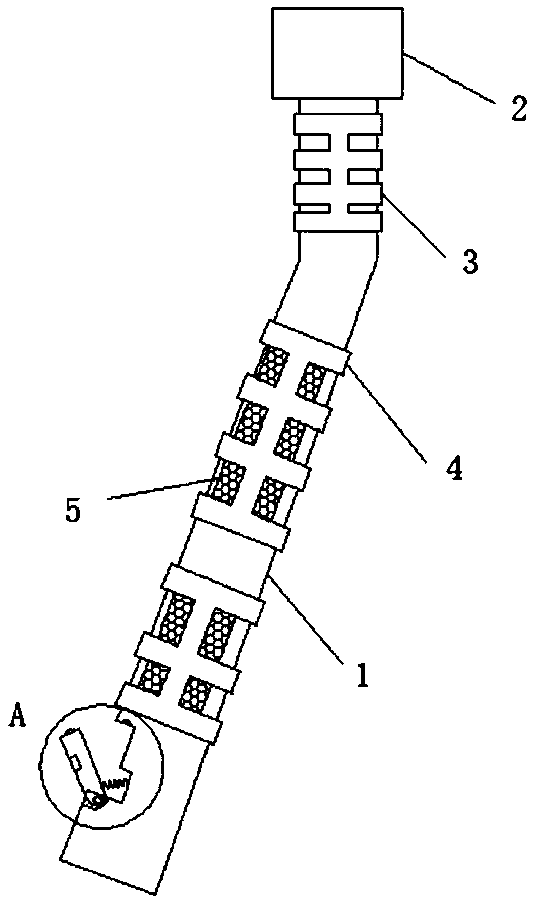
[0018] see Figure 1 to Figure 3 As shown, a tool handle for a dental drill includes a handle body 1 and a tool seat 2, one end of the handle body 1 is provided with a tool seat 2, one end of the handle body 1 is sleeved with a first rubber sleeve 3, and the middle part of the handle body 1 is sleeved The second rubber cover 4, and the inside of the second rubber cover 4 is provided with a number of sweat-absorbing cotton 5, the other end of the handle body 1 is provided with an inner groove 8, and the inner groove 8 is movably connected to the support plate 6, and the user uses the tool holder 2 to install the drill of the dental drill. When the user holds the middle part of the handle body 1, the user contacts the handle body 1 through the second rubber sleeve 4, and when holding one end of the handle body 1 with fingers, the user contacts the handle body 1 through the first rubber sleeve 3. When the palm of the hand holds the middle part of the handle body 1, it is easy to ...
Embodiment 2
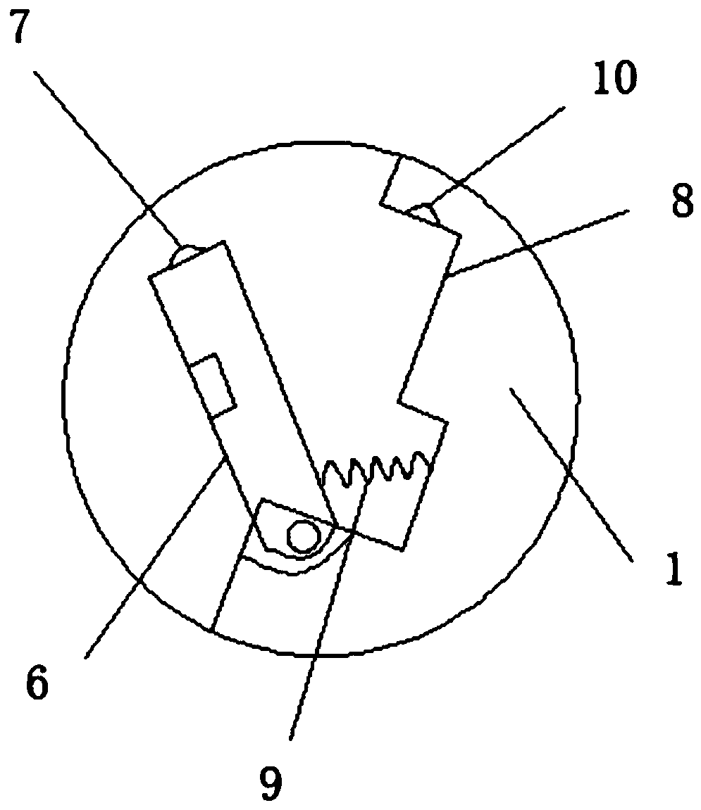
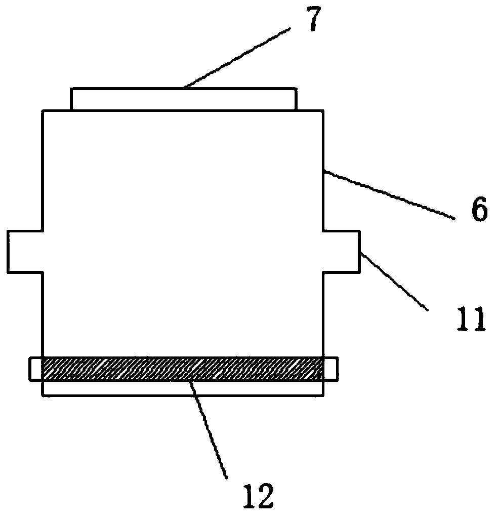
[0020] In addition, refer to Figure 1 to Figure 3 As shown, the difference between this implementation and implementation 1 is that: one end of the support plate 6 is provided with a block 7, the other end of the support plate 6 is provided with a connecting shaft 12, and the support plate 6 is connected to the inner groove 8 through the connecting shaft 12, and one end of the inner groove 8 is provided with a bottom Groove, spring 9 is set inside the bottom groove, and spring 9 one end connects support plate 6, spring 9 other end connects bottom groove bottom, inner groove 8 other ends are provided with draw-in groove 10, and support plate 6 edges are provided with two shifting blocks 11. The support plate 6 matches the inner groove 8 . The first rubber sheath 3 and the second rubber sheath 4 both have a mesh structure, and the sweat-absorbing cotton 5 is arranged in the gap of the second rubber sheath 4 . The locking block 7 is an arc-shaped protrusion structure, the locki...
PUM
 Abstract
Description
Claims
Application Information
 - R&D Engineer
- R&D Manager
- IP Professional
- Industry Leading Data Capabilities
- Powerful AI technology
- Patent DNA Extraction
Browse by: Latest US Patents, China's latest patents, Technical Efficacy Thesaurus, Application Domain, Technology Topic.
© 2024 PatSnap. All rights reserved.Legal|Privacy policy|Modern Slavery Act Transparency Statement|Sitemap