Pulverizer main shaft assembly and pulverizer

A pulverizer and spindle technology, which is applied in the field of pulverizers, can solve problems such as low pulverization efficiency, and achieve the effects of increasing production capacity, reducing load force, and reducing motor power

Pending Publication Date: 2019-02-15
李和军
View PDF7 Cites 3 Cited by
  • Summary
  • Abstract
  • Description
  • Claims
  • Application Information

AI Technical Summary

Problems solved by technology

[0009] The purpose of the first aspect of the present invention is to provide a pulverizer sp

Method used


Image

  • Pulverizer main shaft assembly and pulverizer
  • Pulverizer main shaft assembly and pulverizer

Examples


Embodiment Construction

[0029] In order to make the purpose, technical solution and advantages of the present invention clearer, the technical solution of the present invention will be described in detail below. Apparently, the described embodiments are only some of the embodiments of the present invention, but not all of them. Based on the embodiments of the present invention, all other implementations obtained by persons of ordinary skill in the art without making creative efforts fall within the protection scope of the present invention.

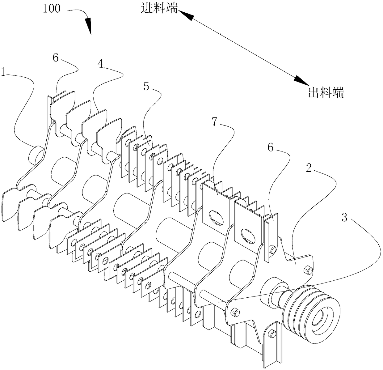
[0030] The first aspect of the present invention provides a pulverizer spindle assembly 100, including a spindle 1, a plurality of hammer brackets 2, a plurality of passing shafts 3, a plurality of guide vanes 4 and a plurality of a hammer 5. A plurality of hammer brackets 2 are fixedly sleeved on the main shaft 1 . A plurality of through shafts 3 are fixedly and fixedly passed through the hammer support 2 along the circumferential direction of the hammer supp...


PUM


Abstract

The invention provides a pulverizer main shaft assembly and a pulverizer, and relates to the technical field of pulverizers. The technical problem that the pulverizing efficiency is low is solved. Thepulverizer main shaft assembly comprises a main shaft, a plurality of hammer sheet supports, a plurality of penetrating shafts, a plurality of guide blades and a plurality of hammer sheets, wherein the guide blades and the hammer sheets are sequentially arranged from the feeding end to the discharging end. The multiple hammer sheet supports fixedly sleeve the main shaft. The multiple penetratingshafts fixedly penetrate through the hammer sheet supports at intervals in the circumferential direction of the hammer sheet supports. The multiple guide blades and the multiple hammer sheets can rotationally sleeve the multiple penetrating shafts and are spirally distributed among the multiple penetrating shafts.

Description

technical field [0001] The invention relates to the technical field of pulverizers, in particular to a pulverizer main shaft assembly and a pulverizer. Background technique [0002] A pulverizer is a machine that crushes large-sized solid raw materials into required sizes. The pulverizer is composed of coarse crushing, fine crushing, wind conveying and other devices, and achieves the purpose of the pulverizer in the form of high-speed impact. [0003] However, in the prior art, the raw material is crushed by the rotating spindle of the pulverizer in the working chamber of the pulverizer, and the pulverized material formed is filtered by a screen and then output to the working chamber. The screen is welded in the middle and lower part of the working chamber. A hammer for hammering materials is fixedly connected to the main shaft. [0004] The applicant finds that the prior art has at least the following technical problems: [0005] 1. The main shaft of the pulverizer is o...

Claims


Application Information

Patent Timeline
IPC IPC(8): B02C13/06B02C13/286B02C13/28
CPCB02C13/06B02C13/2804B02C13/286B02C2013/28609
Inventor 李和军
Owner 李和军
Why Eureka
Try Eureka