Check patentability & draft patents in minutes with Patsnap Eureka AI!

Electrostatic atomization device

A technology of electrostatic atomization and conductive sheets, which is applied in the direction of electrostatic spraying devices, spray discharge devices, spraying devices, etc., can solve the problems of low water delivery efficiency, achieve fast flow speed, improve electrostatic spraying efficiency, and increase condensed water flow Effect

Pending Publication Date: 2019-02-15
AUPU HOME STYLE CORP LTD
View PDF2 Cites 3 Cited by
  • Summary
  • Abstract
  • Description
  • Claims
  • Application Information

AI Technical Summary

Problems solved by technology

[0005] The present invention aims at the low water delivery efficiency of the existing electrostatic atomization device using condensed water source, and provides an electrostatic atomization device different from the prior art, which can also generate electrostatic atomization effect relatively quickly

Method used


Image

  • Electrostatic atomization device
  • Electrostatic atomization device
  • Electrostatic atomization device

Examples


Embodiment 1

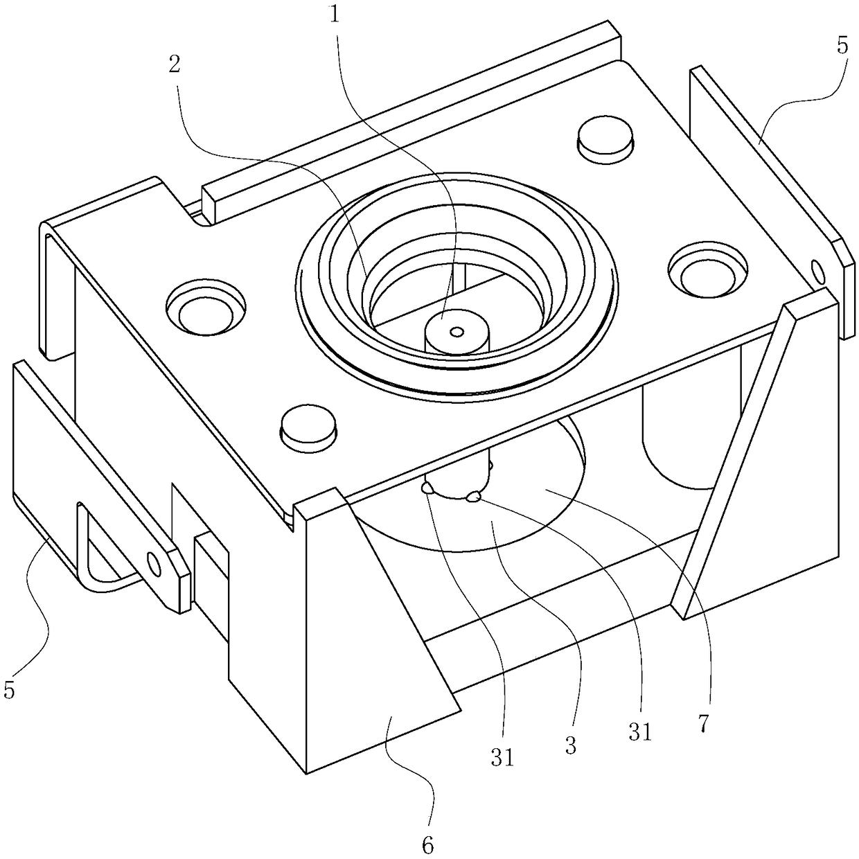
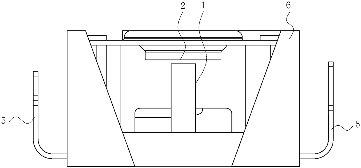
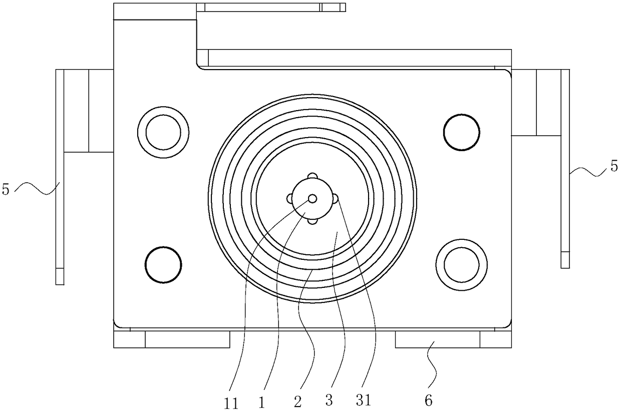
[0053] see Figure 1 to Figure 7 , an electrostatic atomization device according to Embodiment 1 of the present invention, comprising:

[0054] emitter electrode 1;

[0055] The opposite electrode 2, the opposite electrode 2 is opposite to the emitter electrode 1;

[0056] A water supply device, the water supply device provides condensed water 8 to the emitter electrode 1;

[0057] High-voltage power supply, the high-voltage power supply applies high voltage to the emitter electrode 1 and the opposite electrode 2, thereby electrostatically charging the water on the emitter electrode 1, so that the discharge end of the emitter electrode 1 ejects charged water particles;

[0058] The water supplier includes a conductive condensation pan 3 connected to the emitter electrode 1, the condensation water 8 is generated on the upper surface of the condensation pan 3, there is a gap between the condensation pan 3 and the emitter electrode 1, and the emitter electrode 1 has a through h...

Embodiment 2

[0070] The difference between the second embodiment and the first embodiment is that: the emitter electrode 1 is provided with a through capillary groove.

[0071] see Figure 8 to Figure 10 The outer surface of the emitter electrode 1 is provided with a through capillary groove 12, and the condensed water 8 flows from the condensation pan 3 into the capillary groove 12 through capillary action. There are multiple and identical capillary grooves 12 on each emitter electrode 1 , and the plurality of capillary grooves 12 are evenly distributed on the emitter electrode 1 . Specifically, in this embodiment, the number of capillary grooves 12 is four. The cross section of the capillary groove 12 is arc-shaped and the arc angle is greater than 180°.

[0072] Capillary grooves 12 are arranged on the outer periphery of the emitter electrode 1, and more condensed water 8 can be transported in the same time.

[0073] Other structures and effects of the second embodiment are the same ...


PUM


Abstract

The invention belongs to the technical field of electrostatic atomization, and particularly relates to an electrostatic atomization device. The device solves the problem that an existing electrostaticatomization device adopting a condensation water source is low in water conveying efficiency. The electrostatic atomization device comprises an emission electrode, an opposite electrode opposite to the emission electrode, and a water supplying device providing condensate water for the emission electrode; the water supplying device comprises a conductive condensation disc connected with the emission electrode, condensate water is generated on the condensation disc, a gap is arranged between the condensation disc and the emission electrode, a through capillary hole is formed in the emission electrode, and the condensate water flows into the capillary hole from the condensation disc via the gap through the capillary effect. The electrostatic atomization device has the beneficial effects thata dedicated water supply is not needed, the condensate water is generated on the condensation disc and is not generated on the emission electrode, and the condensate water flowing speed is high.

Description

technical field [0001] The invention belongs to the technical field of electrostatic atomization, and in particular relates to an electrostatic atomization device. Background technique [0002] Japanese Patent Publication No. 2005-131549 discloses an electrostatic atomization device that generates charged nano-sized water particles (nano-sized spray). The device is configured to apply a high voltage across the emitter electrode and the counter electrode supplied with water to cause Rayleigh disintegration of the water carried on the emitter electrode, thereby atomizing the water. The thus-obtained charged water particles contain radicals, and remain diffused into the space in large quantities over a long period of time, thereby performing disinfection and deodorization. [0003] However, the water source of the above-mentioned device depends on the heat-absorbing plate to condense the water and then transport it to the emitter electrode through the water delivery unit. The ...

Claims


Application Information

Patent Timeline
Patent Type & Authority Applications(China)
IPC IPC(8): B05B5/025
CPCB05B5/0255
Inventor 高守勇
Owner AUPU HOME STYLE CORP LTD
Features
  • R&D
  • Intellectual Property
  • Life Sciences
  • Materials
  • Tech Scout
  • Unparalleled Data Quality
  • Higher Quality Content
  • 60% Fewer Hallucinations
Learn More