Laser marking assembly

A laser marking and component technology, applied in laser welding equipment, welding equipment, metal processing equipment and other directions, can solve the problems of inability to meet modern production, low marking efficiency, etc., to improve marking efficiency and marking yield rate. Effect

Pending Publication Date: 2019-02-15
GUANGDONG UCAN ROBOT TECH CO LTD
View PDF0 Cites 0 Cited by
  • Summary
  • Abstract
  • Description
  • Claims
  • Application Information

AI Technical Summary

Problems solved by technology

[0002] After the product is manufactured, for example, after the boards such as flexible circuit boards are manufactured, it is often necessary to mark the boards in order to mark the manufactured boards. In the prior art, operators need to hold marking machines to Plates are marked one by one, the marking efficiency is low, and it cannot meet the needs of modern production

Method used


Image

  • Laser marking assembly
  • Laser marking assembly
  • Laser marking assembly

Examples


Embodiment Construction

[0033] In order to facilitate the understanding of those skilled in the art, the present invention will be further described below in conjunction with the embodiments and accompanying drawings, and the contents mentioned in the implementation modes are not intended to limit the present invention.

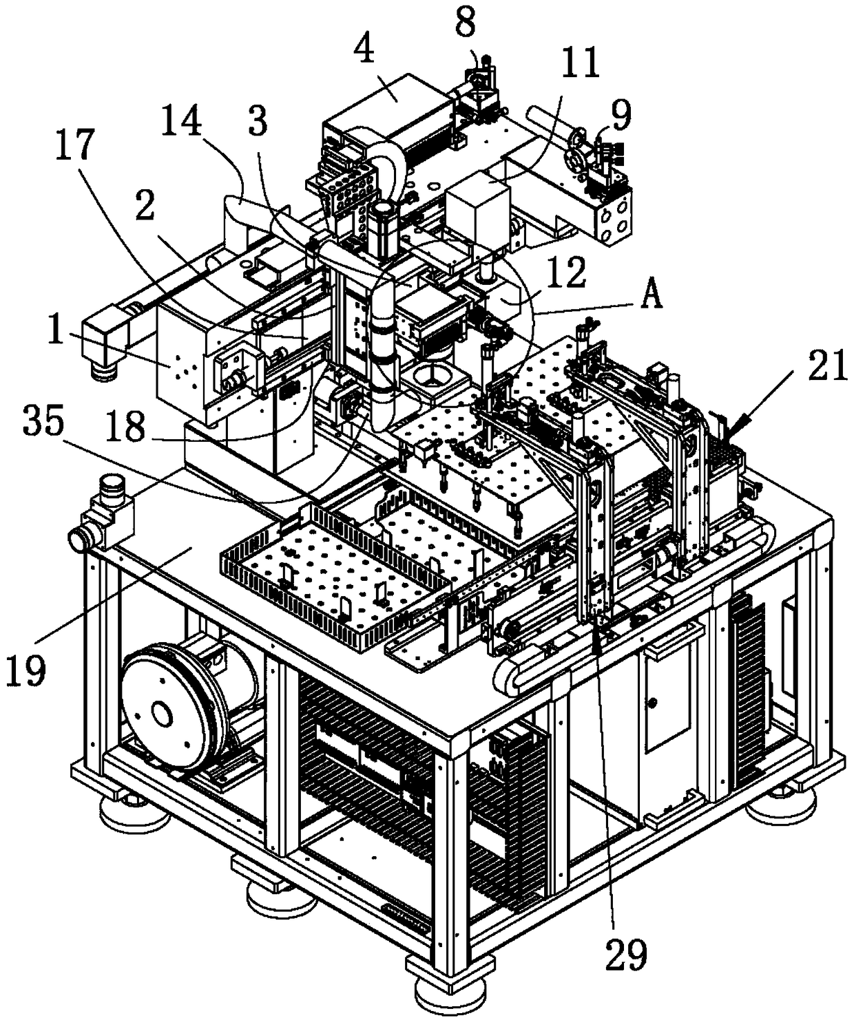
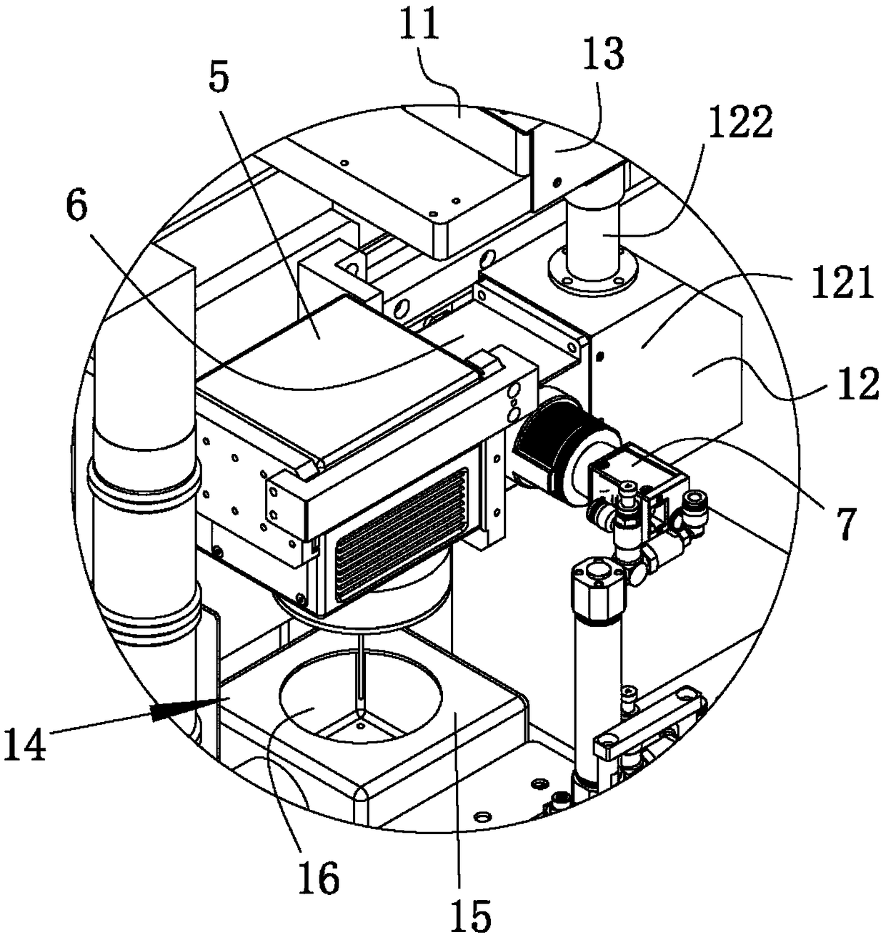
[0034] see figure 1 and figure 2 As shown, a laser marking assembly of the present invention includes a first bracket 1, a first board 2 slidably arranged on the first bracket 1, and is arranged on the first bracket 1 and is used to drive the first board 2 along the The first driver that slides back and forth in the horizontal direction, the second plate 3 that is slidably arranged on the first plate 2, and the second plate that is arranged on the first plate 2 and used to drive the second plate 3 to slide back and forth in the vertical direction Two drivers; also include laser generator 4, laser head assembly 5, light coaxial device 6 and industrial camera 7, light coaxial device...


PUM


Abstract

The invention relates to the technical field of plate marking, in particular to a laser marking assembly. The laser marking assembly comprises a first bracket, a first plate body and a second plate body, wherein the first plate body and the second plate body are slidably arranged on the first bracket; the laser marking assembly further comprises a laser generator, a laser head assembly, a light coaxial device and an industrial camera; laser light emitted by the laser generator is emitted out through the light coaxial device and the laser head assembly; and the light coaxial device is used forcombining the laser light emitted by the laser head assembly with shooting light of the industrial camera into coaxial light. During actual application, the industrial camera captures an image of an outside plate through the light coaxial device and the laser head assembly, the industrial camera is focused according to the thickness of the plate in cooperation with movement of the first plate bodyand the second plate body, thus, the industrial camera captures the clear image, the laser generator emits laser light from the laser head assembly to mark the plate photographed by the industrial camera after focusing, automatic laser marking of the plate is achieved, the plate marking efficiency is improved, and the marking yield is increased.

Description

technical field [0001] The invention relates to the technical field of plate marking, and in particular discloses a laser marking component. Background technique [0002] After the product is manufactured, for example, after the boards such as flexible circuit boards are manufactured, it is often necessary to mark the boards in order to mark the manufactured boards. In the prior art, operators need to hold a marking machine to Plates are marked one by one, and the marking efficiency is low, which cannot meet the needs of modern production. Contents of the invention [0003] In order to overcome the shortcomings and deficiencies in the prior art, the object of the present invention is to provide a laser marking assembly, which adjusts the focus of the industrial camera in conjunction with the movement of the first board and the second board according to the thickness of the board, so that The industrial camera shoots a clear image, and the laser generator emits laser light...

Claims


Application Information

Patent Timeline
IPC IPC(8): B23K26/362B23K26/70B23K26/03B23K26/16B23K26/064
CPCB23K26/032B23K26/064B23K26/0643B23K26/16B23K26/361B23K26/362B23K26/702
Inventor 王俊锋唐凌志杨小兵王海涛李建华杜红岩
Owner GUANGDONG UCAN ROBOT TECH CO LTD
Why Eureka
Try Eureka