Method and device for limiting vehicle speed, and overall vehicle

A technology of limiting vehicle speed and limit value, which is applied in the automotive field, can solve the problems of heavy calibration workload and low accuracy of vehicle speed control, and achieve the effect of less workload, short adjustment period and simple method

Active Publication Date: 2019-02-15
WEICHAI POWER CO LTD
View PDF6 Cites 6 Cited by
  • Summary
  • Abstract
  • Description
  • Claims
  • Application Information

AI Technical Summary

Problems solved by technology

Since the weight of the vehicle directly affects the torque of the engine corresponding to the same vehicle speed, for example, the torque required by the same vehicle speed is different under the conditions of no-load, light-load, and heavy-load, so the existing control strategy cannot take into account different vehicle speeds. The torque required by the weight of the vehicle can only be calibrated repeatedly under various vehicle loads to meet the requirements of the vehicle speed limit value as much as possible, resulting in a very large calibration workload and relatively low accuracy of vehicle speed control

Method used


Image

  • Method and device for limiting vehicle speed, and overall vehicle
  • Method and device for limiting vehicle speed, and overall vehicle
  • Method and device for limiting vehicle speed, and overall vehicle

Examples


Embodiment Construction

[0050] The present invention will be further described in detail below in conjunction with the accompanying drawings and embodiments. It should be understood that the specific embodiments described here are only used to explain the present invention, but not to limit the present invention. In addition, it should be noted that, for the convenience of description, only some structures related to the present invention are shown in the drawings but not all structures.

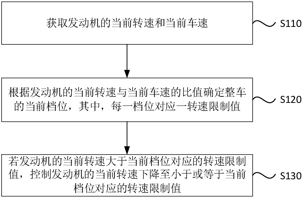
[0051] figure 1 It is a flow chart of a method for limiting vehicle speed provided by the embodiment of the present invention. This embodiment is applicable to problems such as when the engine of the whole vehicle has a serious failure and the emission exceeds the limit, or when the vehicle speed signal may be lost during actual operation of the whole vehicle. Condition. The method can be executed by a vehicle speed limiting device, and the vehicle speed limiting device can be integrated in the vehicle ECU. Such...


PUM


Abstract

The invention discloses a method and a device for limiting vehicle speed, and an overall vehicle. The method for limiting the vehicle speed comprises the following steps of: acquiring the current rotating speed of an engine and the current vehicle speed; determining the current gear of the overall vehicle according to the ratio of the current rotating speed of the engine to the current vehicle speed; and if the current rotating speed of the engine is larger than a rotating speed limit value corresponding to the current gear, controlling the current rotating speed of the engine to be reduced toa value which is smaller than or equal to the rotating speed limit value corresponding current gear. According to the method disclosed by the invention, the torque information required by the overallvehicle at the current gear can be directly calculated according to that different gears correspond to different rotating speed limit values, thus the fuel-injection quantity required by the engine when the vehicle speed is limited to be equal to a regulation stated vehicle speed limit value can be accurately output, and accurate control of the vehicle speed is realized. Meanwhile, in the controlprocess, the final output torque information when the overall vehicle is at different gears is directly determined according to the determined rotating speed limit value; a dynamic regulation processis not needed; the method is simple; the regulation process needs small workload; and the regulation period is short.

Description

technical field [0001] The embodiments of the present invention relate to the technical field of automobiles, and in particular to a method, a device and a complete vehicle for limiting the speed of a vehicle. Background technique [0002] At present, for national VI commercial vehicles, the regulations require that when a serious engine failure causes exhaust emissions to exceed the standard, the speed of the vehicle needs to be limited to no more than 20km / h. Therefore, the electronic control unit (Electronic Control Unit, ECU) control strategy should add the function of the engine to actively limit the vehicle speed when serious emission-related faults occur. On Board Diagnostics (OBD) can give an alarm in time and limit the vehicle speed to no more than 20km / h. In order to meet the requirements of the regulations on the speed limit of the faulty vehicle, it is also necessary to consider the possible loss of the vehicle speed signal during the actual operation of the veh...

Claims


Application Information

Patent Timeline
Patent Type & Authority Applications(China)
IPC IPC(8): B60K31/00
CPCB60K31/00B60K2031/0091
Inventor 冯春涛张成国朱兴军殷月祥孙振杰
Owner WEICHAI POWER CO LTD
Why Eureka
Try Eureka