Charging pile

A technology of charging piles and charging lines, which is applied in charging stations, electric vehicle charging technology, electric vehicles, etc., can solve the problems of convenient power supply line collection and lack of power supply line protection, and achieve the effect of good operation convenience

Active Publication Date: 2019-02-15
海南中科共创新能源有限公司
View PDF6 Cites 5 Cited by
  • Summary
  • Abstract
  • Description
  • Claims
  • Application Information

AI Technical Summary

Problems solved by technology

The current charging piles are still lacking in the convenience of retracting the power supply lines and the protection of the power supply lines.

Method used


Image

  • Charging pile
  • Charging pile
  • Charging pile

Examples


Embodiment 1

[0034] Embodiment 1: as Figure 1 to Figure 9 as shown in

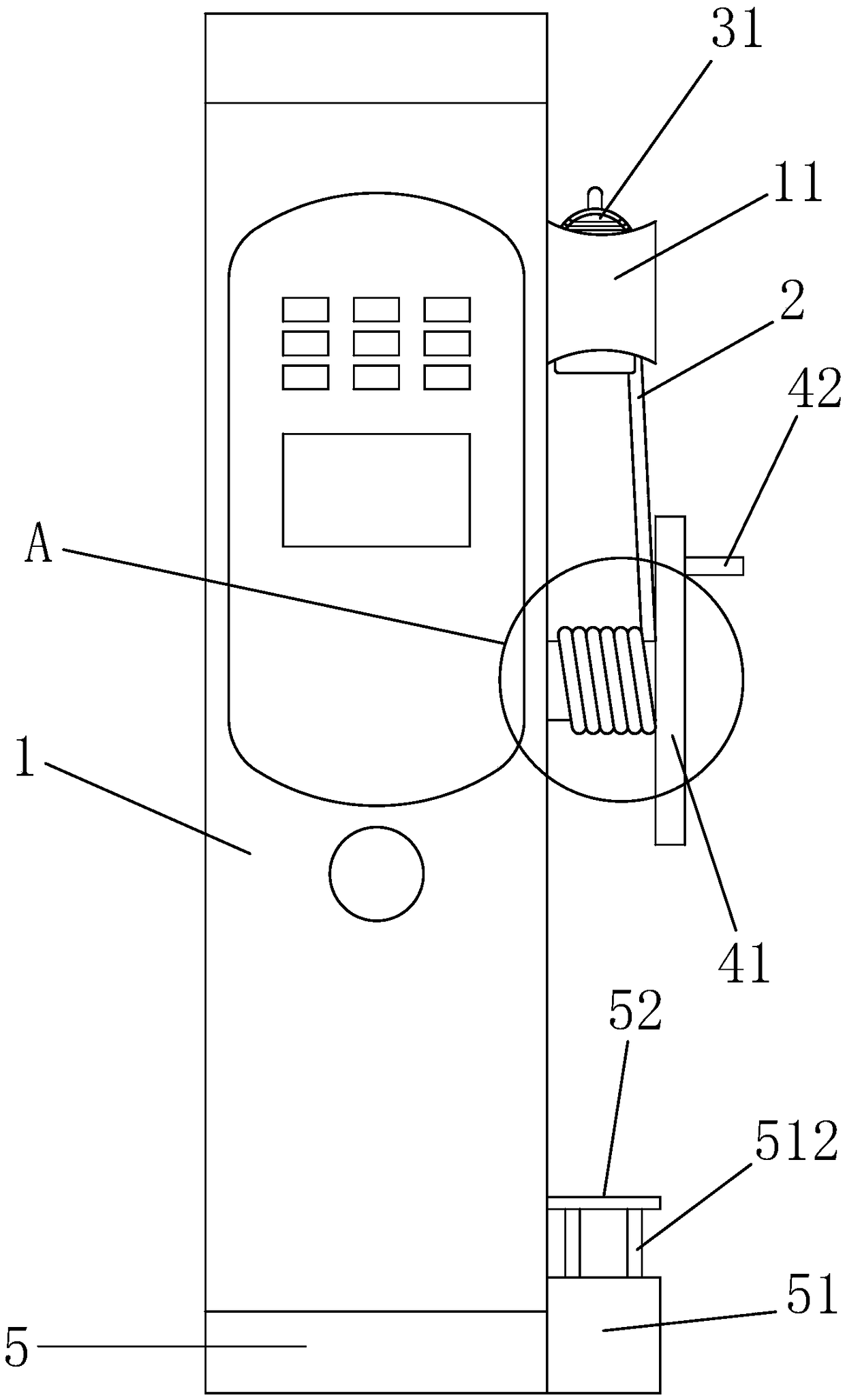
[0035] A charging pile, including a pile body 1 and a charging circuit;

[0036] The charging circuit includes a power supply line 2 and an output socket 3 for docking with the input socket of the electric vehicle. The output socket is electrically connected to the power supply line. The output socket includes a socket base 31 and a socket barrel 32. One end of the socket barrel is open, and the socket barrel is another One end is sealed by the socket base, and a conductive pin 321 is arranged in the socket barrel;

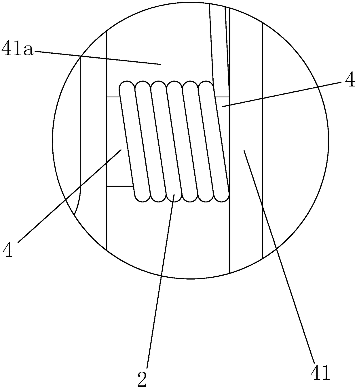
[0037] The pile body is provided with an inner cavity, and the pile body is provided with a rotating shaft 4 that is rotatably connected to the pile body. The rotating shaft and the pile body are rotated and sealed. The turntable 41 outside the main body forms a winding space 41a between the turntable and the pile body, a connecting buckle is provided on the power supply line, and the connecting buckle ...

Embodiment 2

[0051] Embodiment 2: based on embodiment 1, as Figure 10 to Figure 12 as shown,

[0052] The sleeve outer cover is provided with a swivel 81 that is rotatably connected with the sleeve, the swivel is provided with a pin lifting magnet 82, and the other end of the small diameter pin is provided with a passive magnet 83 that can be absorbed by the pin lifting magnet. Always stay outside the small diameter hole. The swivel is provided with a counterweight 84, and the passive magnetic block is fixed on the swivel through the counterweight. In this embodiment, when it is necessary to pull out the positioning pin (the lower end of the large-diameter pin leaves the positioning slot), the swivel can be turned directly so that the pin lifting magnet reaches the top, and the passive magnetic block is absorbed and moved up, driving the positioning pin to leave the positioning slot . Compared with directly pulling out the positioning pin upwards (the lower end of the large-diameter pi...


PUM


Abstract

The invention discloses a charging pile comprising a pile body and a charging line, wherein an inner cavity is arranged inside the pile body; the pile body is provided with a rotating shaft rotationally connected to the pile body; the rotating shaft is in rotating and sealing cooperation with the pile body; one end of the rotating shaft is positioned in the inner cavity; the other end of the rotating shaft is provided with a rotating disk positioned outside the pile body; a wire winding space is formed between the rotating disk and the pile body; a power supply wire is provided with a connecting fastener; the connecting fastener is connected to the rotating shaft; a locking frame is arranged at the outer side wall of the pile body; an output socket is engaged with the locking frame; and asocket base is positioned above a socket cylinder. The charging pile has the beneficial effects of effectively charging electric vehicles, winding and protecting the power supply wire, and enabling the operation of releasing the power supply wire and retracting the power supply wire to be extremely efficient. The charging pile has an automatic locking function, and the unlocking operation and theoperation of releasing and retracting the power supply wire can be completed by hands and feet at the same time. The operation is convenient.

Description

technical field [0001] The invention belongs to the technical field of electric vehicles, in particular to a charging pile. Background technique [0002] With the development of the field of electric vehicles, charging piles for electric vehicles have become more and more common. The function of charging piles is similar to that of fuel dispensers in gas stations. They can be fixed on the ground or walls and installed in public environments, residential areas, and charging stations. wait. The input end of the charging pile is directly connected to the AC grid, and the output end of the charging pile is equipped with a charging end structure that matches the input socket of the electric vehicle, and the charging end structure is connected to the input end through a power supply line. When in use, the position and length of the power supply line need to be adjusted according to the position of the electric vehicle and charging pile. After use, the power supply line needs to b...

Claims


Application Information

Patent Timeline
Patent Type & Authority Applications(China)
IPC IPC(8): B60L53/31B60L53/18
CPCY02T10/70Y02T10/7072Y02T90/12Y02T90/14
Inventor 陈志君
Owner 海南中科共创新能源有限公司
Why Eureka
Try Eureka