Multifunctional trash can

A trash can and multi-functional technology, applied in the field of daily necessities, can solve the problems of single function, large amount of activated carbon, limited adsorption capacity of activated carbon, etc., and achieve the effect of prolonging the service life.

Inactive Publication Date: 2019-02-15
肖华林
View PDF0 Cites 1 Cited by
  • Summary
  • Abstract
  • Description
  • Claims
  • Application Information

AI Technical Summary

Problems solved by technology

However, the inventors have found that the activated carbon adsorption method is limited due to the limited adsorption capacity of activated carbon, and the activated carbon bag needs to be replaced frequently, which is inconvenient and requires a large amount of activated carbon.
In addition, the existing trash can has a single function

Method used


Image

  • Multifunctional trash can
  • Multifunctional trash can
  • Multifunctional trash can

Examples


Embodiment 1

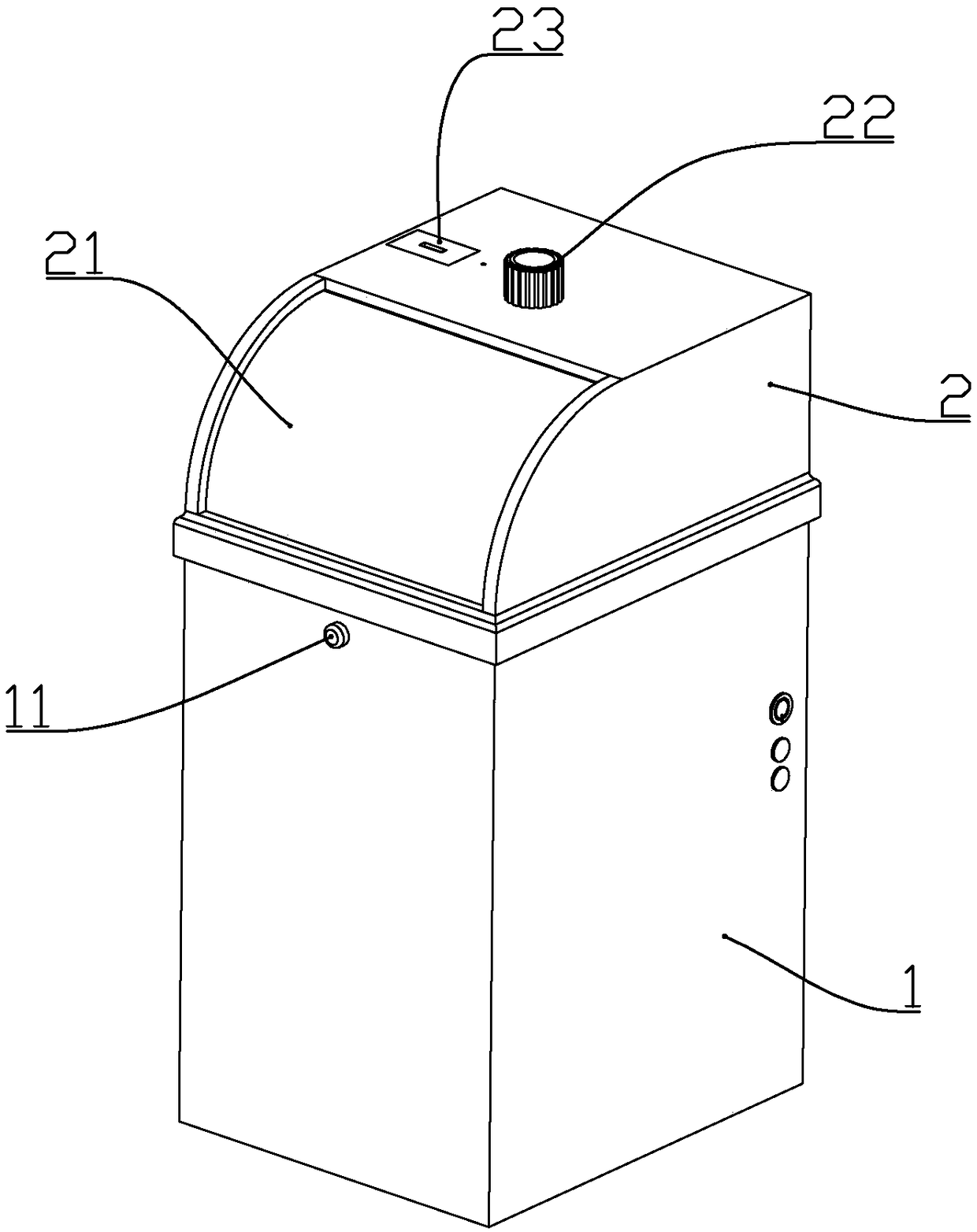
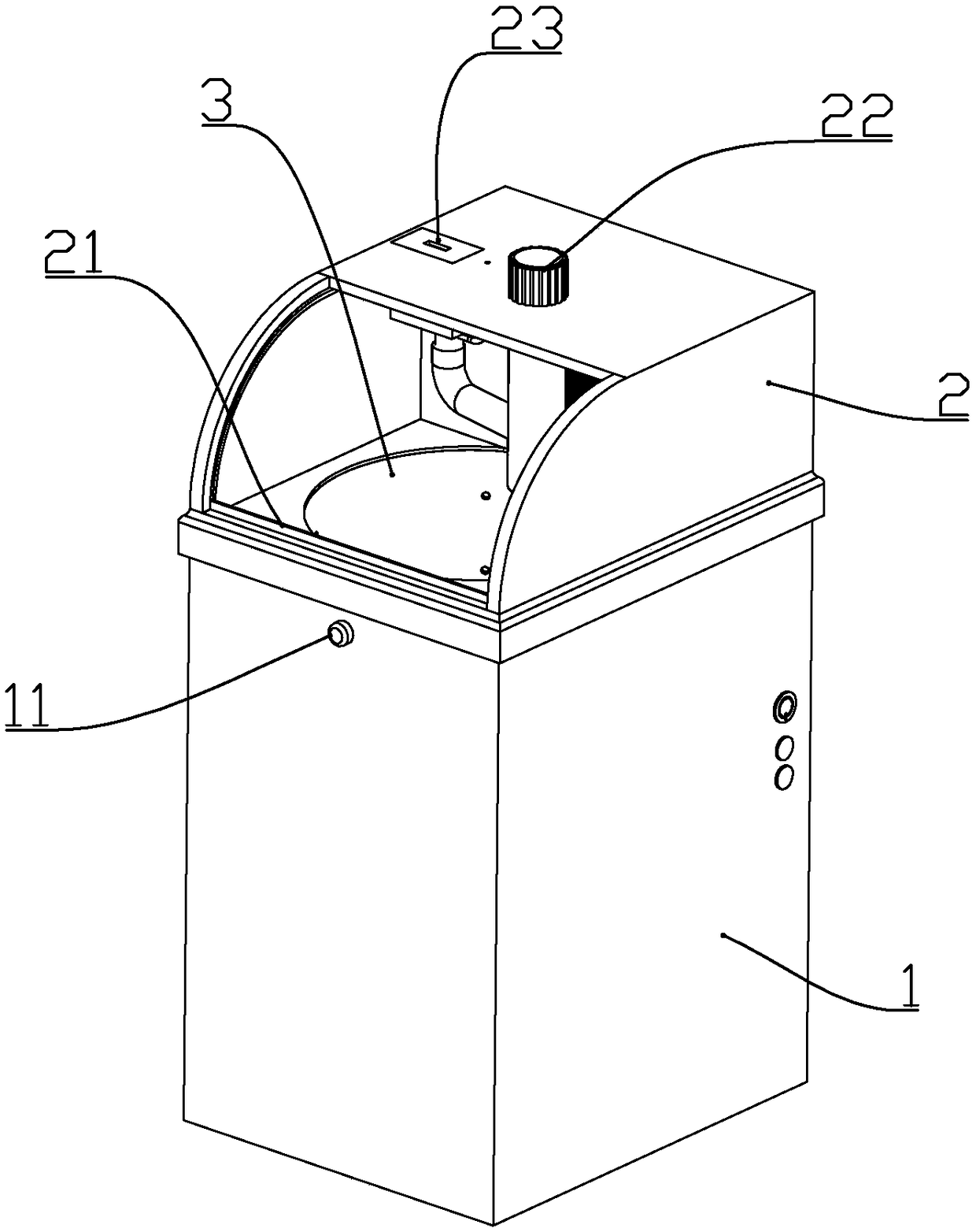
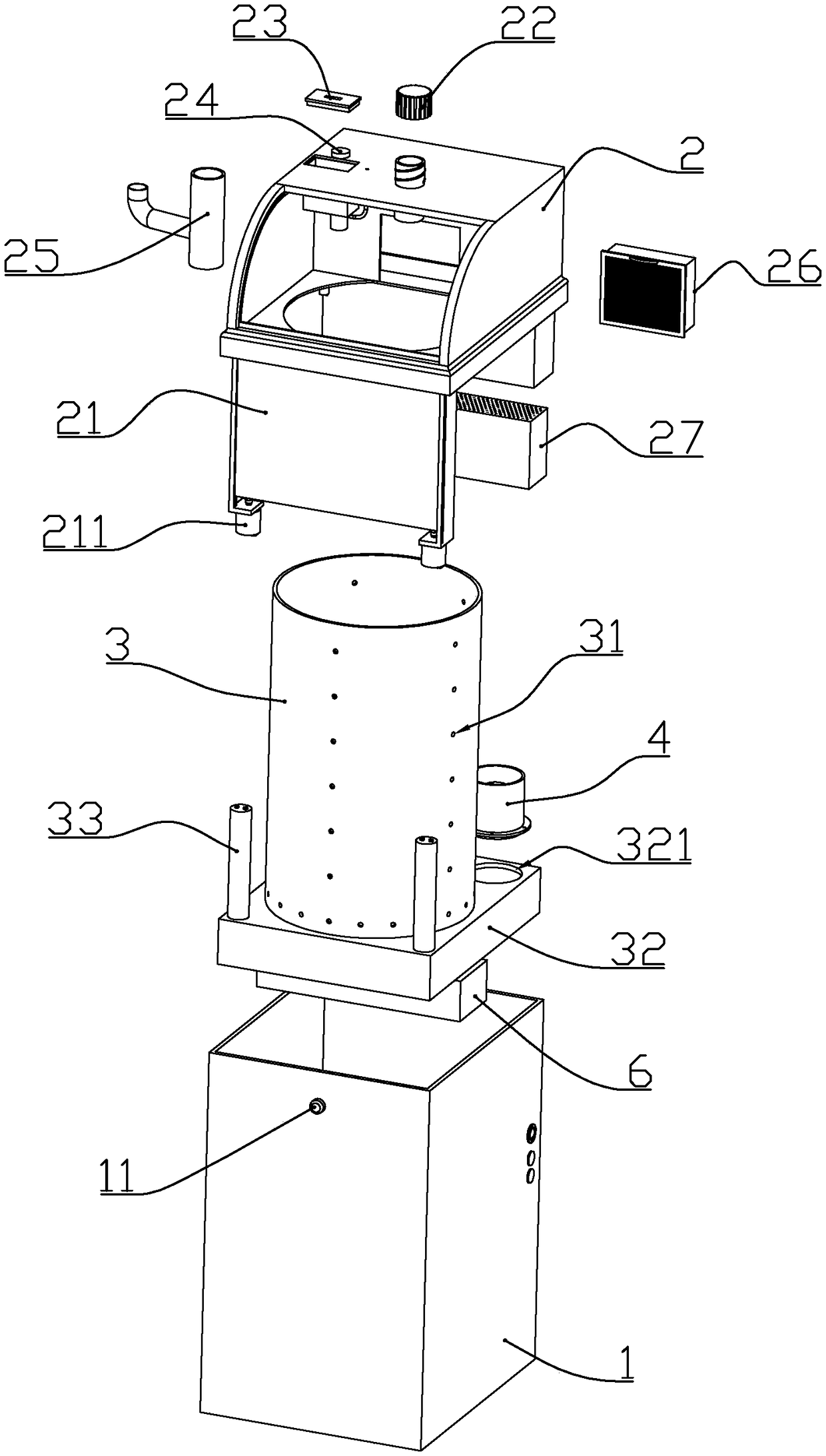
[0042] according to Figure 1 to Figure 8As shown, the present embodiment is a multifunctional trash can, comprising a cuboid-shaped outer barrel 1 with an open upper end, a cylindrical inner barrel 3 installed in the outer barrel from top to bottom, and a detachably sleeved upper end of the outer barrel The barrel lid 2.

[0043] The lower end of the inner barrel is integrally connected with a lower support 32 that matches the shape of the inner circumference of the outer barrel. Two fans 4 that supply air from top to bottom are installed on the upper end of the rear side of the lower support. A fan installation port 321 is formed at the position where the fan is installed; an air exhaust port 12 is formed at the lower end of the rear wall of the outer barrel, and the lower part of the lower support is connected to the air exhaust port.

[0044] The front upper part of the lid is formed with an arc-shaped garbage throwing inlet, and the two sides of the garbage throwing inle...

Embodiment 2

[0056] combine Figure 1 to Figure 10 As shown, the present embodiment makes the following improvements on the basis of embodiment 1:

[0057] A dust suction pipe 201 is formed on the lid above the inner barrel, and the upper end of the dust suction pipe is connected with a cover 22 through threads, or connected with a dust suction head 5 through a hose 51 .

[0058] An atomizing water tank 202 is formed at the top of the barrel cover at a position different from that of the suction pipe, and an ultrasonic microporous atomizer 24 is installed at the bottom of the atomizing water tank; There is a mist outlet pipe 2021, an air suction pipe 203 is connected to the side of the mist outlet pipe, and the other end of the air suction pipe extends outside the barrel cover; the upper end of the atomization water tank is connected to a water tank cover 23.

[0059] A humidification pipe 25 is connected to the lower end of the suction pipe, and the lower end of the humidification pipe i...

Embodiment 3

[0069] combine Figure 11 , Figure 12 In this embodiment, the following improvements are made on the basis of Embodiment 1 or 2: a support bead 35 is formed on the upper periphery of the inner barrel, and a rotating ring 7 is provided on the outer periphery of the inner barrel above the support bezel. The outer wall of the rotating ring 7 is formed with 5-8 groups of wheel seats 701, and each group of wheel seats is connected with a sticky wheel 702 made of thermoplastic material or soft silicone material through a pin shaft, and between the sticky wheel and the pin shaft is The interference fit makes the viscous wheel need to overcome the frictional force when rotating relative to the pin shaft; the outer wall of the rotating ring is located under the wheel seat and formed with driven teeth 703, and the inner wall of the outer barrel is equipped with a sealing motor 71 that drives the rotating ring to rotate , the output shaft of the sealing motor is connected with a drive ...


PUM


Abstract

The invention discloses a multifunctional trash can comprising an outer barrel, a cylindrical inner barrel installed in the outer barrel, and a barrel cover arranged at the upper end of the outer barrel in a sleeving manner. The lower end of the inner barrel is integrally connected with a lower support matched with the inner circumference shape of the outer barrel. Two fans are installed at the upper end of the rear side of the lower support. Fan installation openings are formed in the positions, provided with the fans, on the lower support. An exhaust outlet is formed in the position of the lower end portion of the rear wall face of the outer barrel. An arc-shaped trash thrown-in opening is formed in the upper front portion of the barrel cover. Baffle guide grooves are symmetrically formed in the portions, located on the two sides of the trash throw-in opening, on the barrel cover. An elastic baffle used for sealing and blocking the trash throw-in opening is installed between the twobaffle guide grooves in the two sides in a sliding manner. A pyroelectric sensor used for detecting whether there is a user approaching or not is installed on the upper portion of the front side of the outer barrel. When the pyroelectric sensor detects that the user approaches, the fans work, the elastic baffle then moves downwards to open the trash throw-in opening, and in this way, the user cannot smell the odor of trash in the trash throwing process.

Description

technical field [0001] The invention belongs to the field of daily necessities, and in particular relates to a household multifunctional trash can. Background technique [0002] In the existing garbage cans with deodorizing function, the general method is to place activated carbon bags in the garbage can to absorb the peculiar smell, or to spray bactericidal liquid in the garbage can to inhibit the reproduction of bacteria and reduce the peculiar smell. However, the inventors found that the activated carbon adsorption method requires frequent replacement of the activated carbon bag due to the limited adsorption capacity of the activated carbon, which is inconvenient and consumes a large amount of activated carbon. In addition, the existing trash can has a single function. Contents of the invention [0003] The technical problem to be solved by the present invention is: aiming at the deficiencies in the prior art, to provide a novel structural design, which can ensure that...

Claims


Application Information

Patent Timeline
Patent Type & Authority Applications(China)
IPC IPC(8): B65F1/14B65F1/08B65F1/06
CPCB65F1/06B65F1/08B65F1/14B65F2210/1026B65F2210/137B65F2210/168
Inventor 不公告发明人
Owner 肖华林
Why Eureka
Try Eureka