
Material guiding groove

A kind of technology of guide trough and trough body

Inactive Publication Date: 2019-02-15
SHAANXI LONGMEN IRON & STEEL
View PDF6 Cites 1 Cited by
  • Summary
  • Abstract
  • Description
  • Claims
  • Application Information

AI Technical Summary

Problems solved by technology

[0002] The belt conveyor is a conveying equipment widely used in coal, mining, building materials, chemical industry and other industries. The function of the material guide groove is to be installed at the material receiving part of the belt conveyor to restrain the material from falling out. This structure is suitable for various powder materials. , the conveying of granular materials, however, after some powdery materials enter the belt conveyor, they accumulate at the bottom of the belt, causing blockage, and will overflow from the material guide groove, and the overflowing materials often cause a lot of dust when the belt conveyor is running. On the one hand, it pollutes the environment and damages the health of workers; on the other hand, it causes a waste of resources. For granular and massive materials, the materials are easily stuck between the sealing plate and the tape surface, resulting in poor sealing and overflow; this also accelerates Reduce the wear of the sealing plate, further reduce the sealing effect, and damage the economic benefits

Method used


Image

  • Material guiding groove

Examples


Embodiment Construction

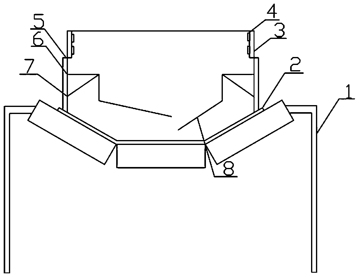
[0012] Such as figure 1 As shown, a feed trough of the present invention comprises a feed trough body and a bracket 1 for supporting the feed trough, and the feed chute body includes lower side plates 5 and The upper side plate 3 that is fixedly connected with the lower side plate 5, the horizontal baffle plate 6 arranged along the horizontal direction on the inside of the lower side plate 5, the horizontal baffle plate 6 passes through the support plate 7 arranged along the inclined direction and the lower side plate 5 Fixedly connected, between the horizontal baffles 6 is a discharge port, the width of the discharge port is smaller than the width between the two lower side plates 5, so that the materials can be piled up in the middle of the belt 2 to prevent the materials from overflowing; The horizontal baffles 6 are all connected with a buffer baffle 8 through a vertical baffle, and the buffer baffles 8 are arranged oppositely, and one of the buffer baffles 8 is arranged a...


PUM


Abstract

The invention belongs to the field of material conveying equipment, and particularly relates to a material guiding groove. The material guiding groove comprises a material guiding groove body and brackets used for supporting the material guiding groove. The material guiding groove is characterized in that the material guiding groove body comprises lower side plates positioned at the two ends of abelt and upper side plates fixedly connected with the lower side plates, the inner sides of the lower side plates are all provided with horizontal material blocking plates in a horizontal direction, the horizontal material blocking plates are fixedly connected with the lower side plates through supporting plates arranged in an inclining direction, a blanking opening is formed between the horizontal material blocking plates, and the width of the blanking opening is smaller than the width between the two lower side plates. According to the material guiding groove, the horizontal material blocking plates are utilized to buffer materials, and concentrated stacking of the materials in the middle region of the belt is achieved, so that material overflow between a sealing plate and the belt and the mechanical wear can be effectively reduced. Due to the arrangement of the buffering material blocking plates, the speed at which the materials fall onto the belt can be reduced, and the direct impact of the materials on the belt is avoided.

Description

technical field [0001] The invention belongs to the field of material conveying equipment, and in particular relates to a material guide trough. Background technique [0002] The belt conveyor is widely used in coal, mining, building materials, chemical and other industries. The function of the guide groove is to install the material at the receiving place of the belt conveyor to restrain the material from falling out. This structure is suitable for various powder materials. 1. The conveying of granular materials. However, after some powdery materials enter the belt conveyor, they accumulate at the bottom of the belt, causing blockage and overflowing from the guide groove. The overflowing materials often cause a lot of dust when the belt conveyor is running. On the one hand, it pollutes the environment and damages the health of workers; on the other hand, it causes a waste of resources. For granular and massive materials, the materials are easily stuck between the sealing pl...

Claims


Application Information

Patent Timeline
Patent Type & Authority Applications(China)
IPC IPC(8): B65G47/18B65G69/00B65D90/00
CPCB65D90/00B65G47/18B65G69/00B65G2207/40B65G2207/28B65G2207/48B65G2201/04
Inventor 彭元飞卫军民马飞段建荣杨建鹏
Owner SHAANXI LONGMEN IRON & STEEL
Learn More