Winding mechanism and power cable winding equipment

A technology of winding mechanism and power cable, which is applied in the field of power cables, can solve problems such as complex structure, inconvenient disassembly and maintenance, and inability to clean cables, and achieve the effect of easy use, convenient disassembly and fixation, and improved cleaning effect

Inactive Publication Date: 2019-02-15
张万里
View PDF9 Cites 9 Cited by
  • Summary
  • Abstract
  • Description
  • Claims
  • Application Information

AI Technical Summary

Problems solved by technology

The structure of the cable retracting and unwinding equipment in the prior art is complicated, it is not easy to disassemble and maintain, the winding efficiency is low, and the cable cannot be cleaned during the cable winding process

Method used


Image

  • Winding mechanism and power cable winding equipment
  • Winding mechanism and power cable winding equipment
  • Winding mechanism and power cable winding equipment

Examples


Embodiment 1

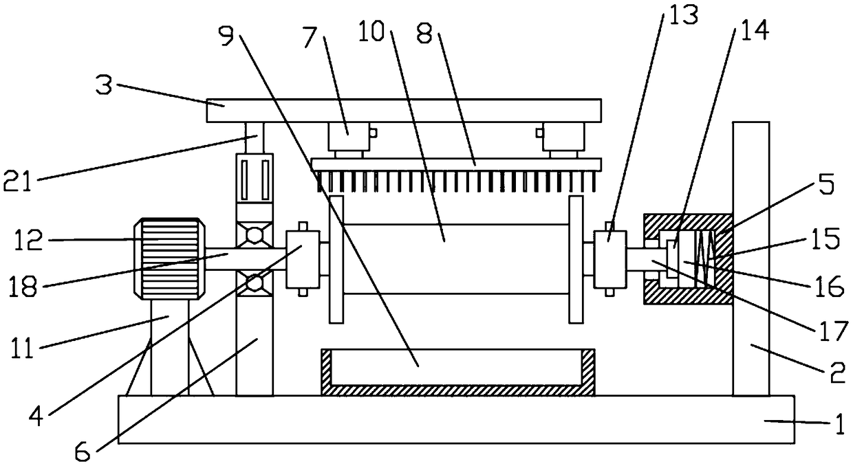
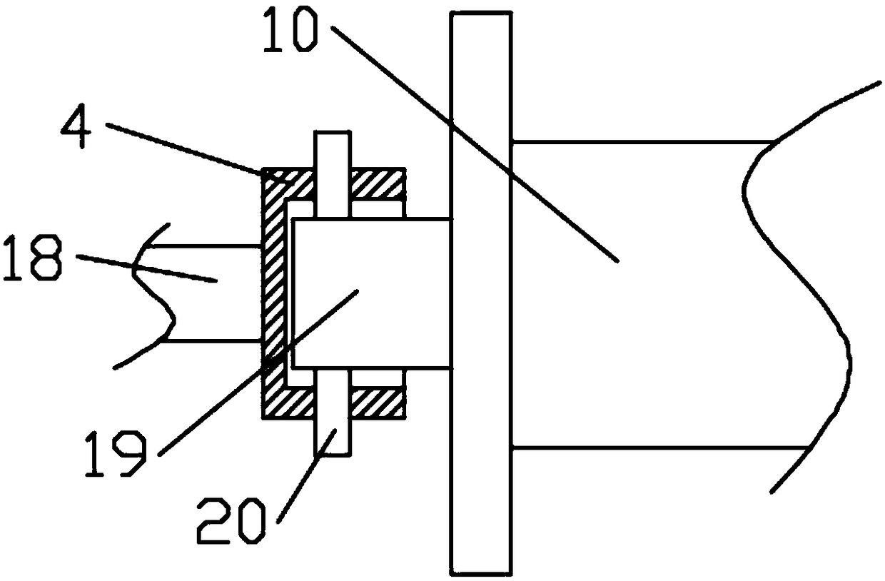
[0022] see figure 1 and figure 2 , in an embodiment of the present invention, a winding mechanism includes a reel 10 and a motor 12 for driving the reel 10 to rotate, and the two ends of the reel 10 respectively pass through the first connection assembly 4 and the second connection assembly 13 Detachable and fixedly installed on the end of the rotating rod 18 and the end of the sliding rod 17, wherein the sliding rod 17 is elastically connected and installed on the first base 5, between the other end of the rotating rod 18 and the output shaft of the motor 12 Drive connection via coupling.

[0023] In the embodiment of the present invention, a cylindrical cavity is provided inside the first base 5, and a first slider 16 cooperating with the cylindrical cavity is slidably arranged in the cylindrical cavity. A first compression spring 15 is provided; a bearing seat 14 is fixedly installed on the left end surface of the first slider 16; the bearing seat 14 is rotationally conn...

Embodiment 2

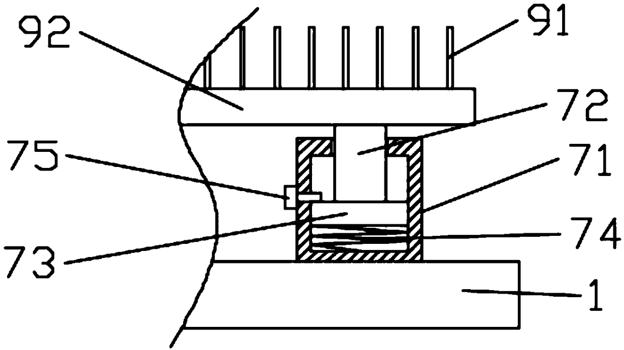
[0031] Unlike Example 1, see figure 1 and image 3 , in the embodiment of the present invention, the cleaning assembly 8 includes the elastic support assembly 7 and the cleaning plate 92 installed on the bottom of the elastic support assembly 7, the lower surface of the cleaning plate 92 is provided with a cleaning brush 91, wherein the elastic support assembly 7 is installed On the lower surface of the support top plate 3, the elastic support assembly 7 includes a second base 71, a support rod 72, a second slider 73, a second spring 74 and a shaft pin 75; the inside of the second base 71 A cylindrical cavity is provided, and a second slider 73 is slidably arranged in the cylindrical cavity, and a second spring 74 is arranged at the bottom of the second slider 73, and the bottom end of the support rod 72 is fixed to the upper surface of the second slider 73 In connection, the outer wall of the second base 71 is also processed with a threaded through hole, and a shaft pin 75 i...


PUM


Abstract

The invention discloses a winding mechanism, which comprises a winding barrel and a motor for driving the winding barrel to rotate. The two ends of the winding barrel are detachably and fixedly mounted at the end of a rotating rod and the end of a sliding rod through a first connecting assembly and a second connecting assembly correspondingly, wherein the sliding rod is mounted on a first base inan elastically connected mode, and the other end of the rotating rod and an output shaft of the motor are in driving connection through a coupling. The invention further relates to power cable windingequipment, the power cable winding equipment comprises a rack, a left supporting vertical column and a right supporting vertical column, wherein the left supporting vertical column and the right supporting vertical column are fixedly mounted on the upper surfaces of the two ends of the rack correspondingly; and the power cable winding equipment further comprises a winding barrel mechanism, and the winding barrel mechanism is fixedly erected and mounted between the left supporting vertical column and the right supporting vertical column. According to the winding mechanism and the power cable winding equipment, disassembly, assembly and fixing of the winding barrel are facilitated, the motor drives the winding barrel to rotate, thus cable winding is achieved, in the cable winding process, acleaning brush is always kept to be in good contact with a cable, and the cleaning effect of the cable is improved.

Description

technical field [0001] The invention relates to the technical field of power cables, in particular to a winding mechanism and power cable winding equipment. Background technique [0002] Electric power engineering refers to engineering related to the production, transmission, and distribution of electric energy. In a broad sense, it also includes engineering that uses electricity as power and energy in various fields. As a form of energy, electric energy has many advantages such as easy conversion, convenient transportation, easy control, easy use, cleanliness and economy. Insufficient electricity seriously hinders the development of the national economy. The experience of various countries in the world shows that the development speed of electric power production should be higher than that of other sectors in order to promote the coordinated development of the national economy. [0003] During the construction of electric power engineering, it is often necessary to lay ca...

Claims


Application Information

Patent Timeline
Patent Type & Authority Applications(China)
IPC IPC(8): B65H54/54B65H54/70B65H75/44
CPCB65H54/54B65H54/702B65H75/44B65H2701/34
Inventor 张万里
Owner 张万里
Why Eureka
Try Eureka