Load detecting device

A technology for detecting equipment and loads, applied in mechanical equipment, measuring force, measuring devices, etc., can solve the problems of difficult detection work, difficult direct implementation of hand-held detection, and affecting bolt performance, etc.

Inactive Publication Date: 2019-02-15
COMAC +1
View PDF5 Cites 1 Cited by
  • Summary
  • Abstract
  • Description
  • Claims
  • Application Information

AI Technical Summary

Problems solved by technology

[0011] When implementing this ultrasonic testing method, the two end faces of the bolt need to be ground flat in advance, which will not only bring difficulties to the testing work, but also may affect the performance of the bolt itself
In addition, because the ultrasonic probe cannot be fixed on the bolt, the handheld ultrasonic testing instrument can only detect the load acting on the bolt in a static state, but cannot complete real-time detection in a moving state
[0012] In addition, the end face of the bolt head of the current standard parts requires the identification code of the part number to be engraved, and the end face of the bolt tail is not flat, so it is difficult to carry out the hand-held inspection objectively.

Method used


Image

  • Load detecting device
  • Load detecting device
  • Load detecting device

Examples


Embodiment Construction

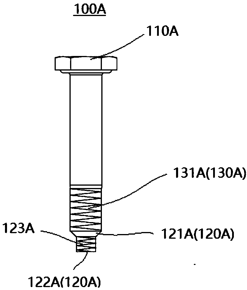
[0084] Hereinafter, referring to Fig. 2(a), Fig. 2(b), Fig. 3(a), Fig. 3(b), Fig. 4(a), Fig. 4(b), Fig. 5(a), Fig. 5(b) , Fig. 6 (a), Fig. 6 (b), Fig. 7 (a), Fig. 7 (b), in conjunction with Fig. 1 (a), the bolt standard part 10 of the prior art shown in Fig. 1 (b), to this The non-standard bolts 100A, 100B, 100C, 100D, 100E, and 100F that can be directly equipped with load detection equipment in the first to sixth embodiments of the invention will be described in detail.

[0085] (bolt standard part 100 of the prior art)

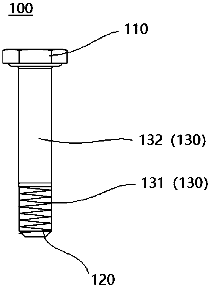
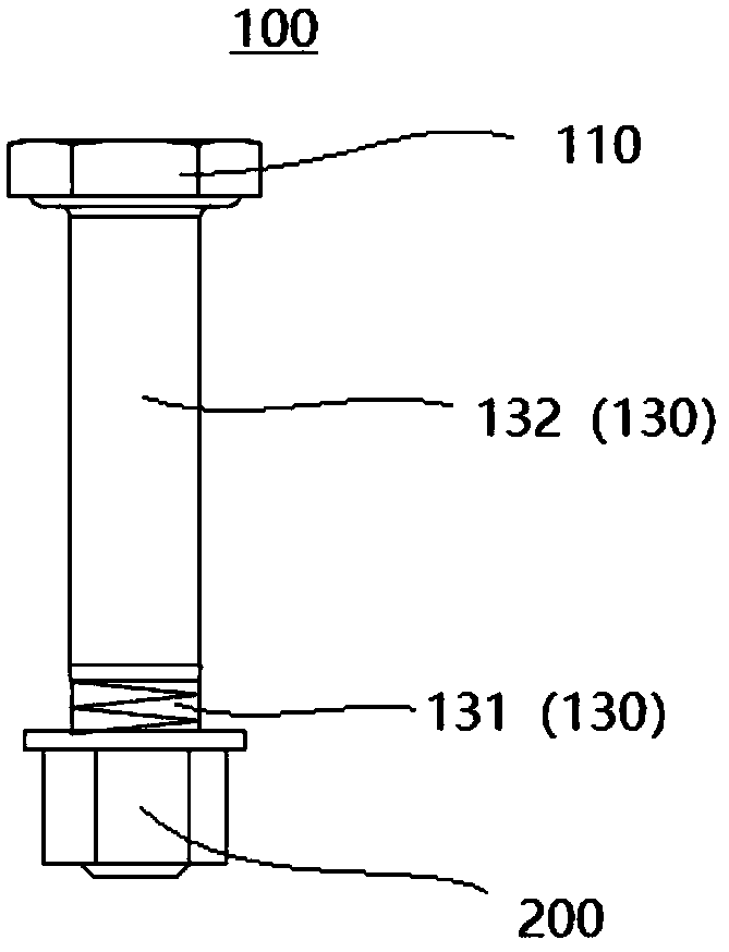
[0086] FIG. 1( a ) is a schematic diagram showing a bolt standard 100 in the prior art, and FIG. 1( b ) is a schematic diagram showing a state in which the bolt standard 100 and the nut standard 200 in the prior art are screwed together.

[0087] As shown in FIG. 1( a ), a standard bolt 100 in the prior art includes a bolt head 110 , a bolt tail 120 and a screw rod 130 .

[0088] In the bolt standard 100 shown in FIG. 1( a ), the bolt head 110 is formed in...


PUM


Abstract

A load detecting device is capable of automatically detecting the load of a bolt, and prompting a real-time condition of the load even if a fixed member to which the bolt is disposed is in a moving state. The load detecting device detects the load on the bolt, characterized by comprising a cover member, a housing as a main body portion of the load detecting device, and an ultrasonic probe. One endside of the housing is covered by the cover member. The ultrasonic probe is disposed on a side of the housing opposite to the cover member. The cover member is provided with a prompting member capable of prompting different states of the load to which the bolt is currently subjected. A control chip with a load algorithm is disposed in the housing. The ultrasonic probe is screwed with an externalthread or an internal thread of the detected bolt, which is dedicated to mounting the ultrasonic probe, by the internal thread or the external thread engraved on the ultrasonic probe, thereby being directly disposed on the bolt.

Description

technical field [0001] The present invention relates to a load detection device, in particular to a load detection device for detecting the load of a bolt. Background technique [0002] As we all know, when the bolt is screwed into the nut after passing through the screw hole of the fixed part, the external thread provided on the screw part is screwed with the internal thread provided on the inner wall of the nut. At this time, the weight of the fixed part acts on the bolt. The screw part, so that the bolt (screw part) bears the load. [0003] If the bolt (screw part) is subjected to an excessive load, the bolt (screw part) will break. Especially in the field of aviation and aerospace where precision machined parts are used, once the bolt (screw part) breaks, the equipment parts will fall off, and the serious safety accident will happen. Therefore, while improving the rigidity of the bolt itself, professionals also pay attention to detecting the load acting on the bolt (sc...

Claims


Application Information

Patent Timeline
Patent Type & Authority Applications(China)
IPC IPC(8): G01L1/25G01L5/00F16B35/04
CPCF16B35/04G01L1/255G01L5/00
Inventor 张松林俞佳
Owner COMAC
Why Eureka
Try Eureka