Visual crack grouting test device and method for simulating multiple main control variables

A grouting test and grouting device technology, applied in the fields of geotechnical engineering and mining engineering, can solve the problems of lack of slurry diffusion and migration law, low hydrostatic pressure, lack of effective control of water environment pressure in aquifers, etc.

Active Publication Date: 2021-01-08
XIAN RES INST OF CHINA COAL TECH& ENG GROUP CORP
View PDF10 Cites 0 Cited by
  • Summary
  • Abstract
  • Description
  • Claims
  • Application Information

AI Technical Summary

Problems solved by technology

[0004] At present, there are the most experiments using a single flat plate fracture to simulate the slurry diffusion law on the dominant fracture surface inside the broken rock and soil, but there are still many shortcomings in this simulation experiment: 1) There is a lack of research on the slurry diffusion and migration law in the original rock or artificial original rock fractures; 2) There is a lack of effective control of the water environment pressure of the aquifer. The existing hydrostatic pressure is generally low, and the hydrostatic pressure is often obtained through the constant head device, which is much lower than the grouting pressure; 3) There is no simulation experiment that considers the grouting pressure, Effects of multiple main control variables such as fracture opening, fracture inclination, fracture roughness, slurry specific gravity, and water pressure environment on slurry migration

Method used


Image

  • Visual crack grouting test device and method for simulating multiple main control variables
  • Visual crack grouting test device and method for simulating multiple main control variables
  • Visual crack grouting test device and method for simulating multiple main control variables

Examples


Embodiment

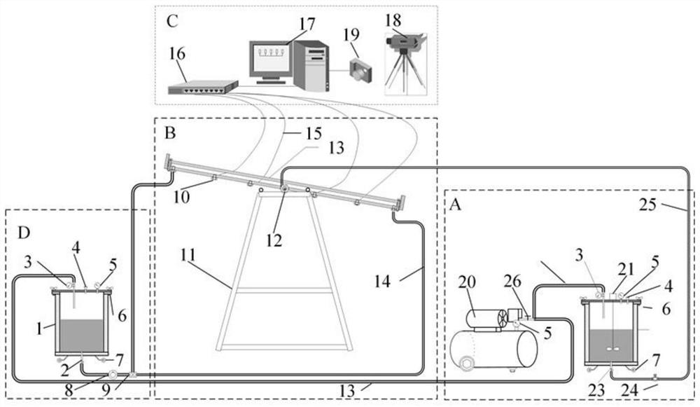
[0048] figure 1 The overall schematic diagram of the Ming experimental device in the embodiment of the present invention is illustrated.

[0049] Please refer to figure 1 , a visual fissure grouting test device for simulating multiple main control variables, including four major systems: A hydraulic constant system, B visual fissure grouting platform, C data acquisition and analysis system, D grouting system.

[0050] The four systems are described below in conjunction with the accompanying drawings.

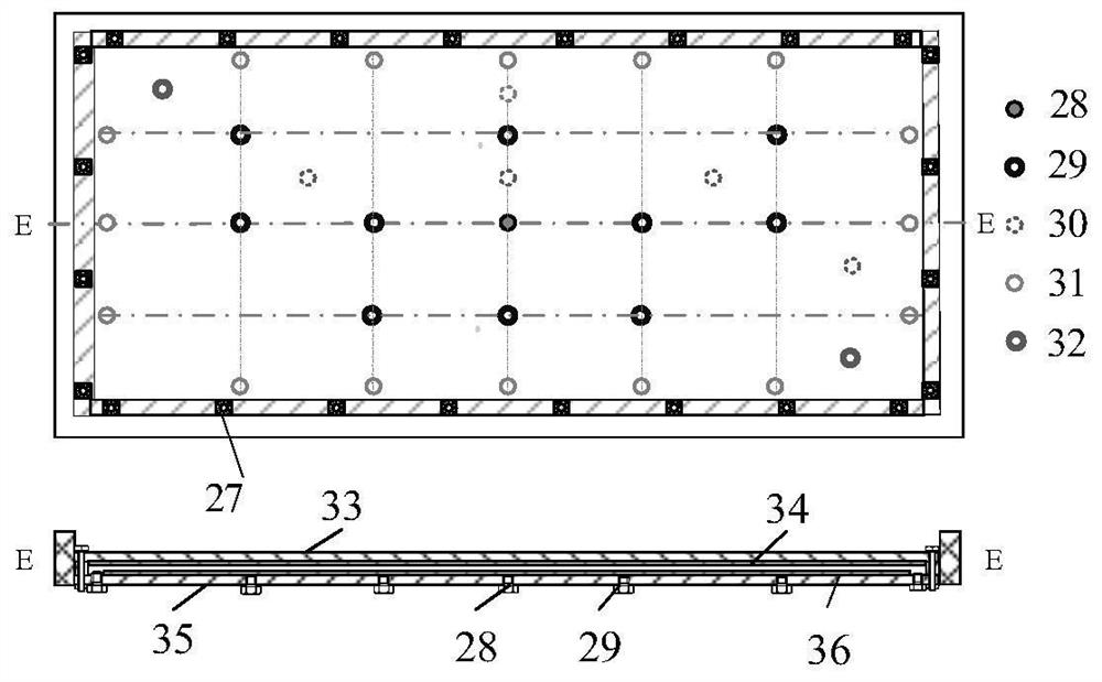
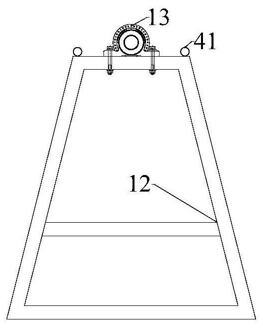
[0051] Such as Figure 2-4 As shown, the visual fissure grouting platform includes: upper cover layer, lower bottom plate, sealing strip, screw fasteners, plate fissure placement base, and angle adjuster. Among them, the upper cover layer has two layers. The first layer of the upper cover is made of plexiglass plate, and its length, width and height are respectively: 1300×700×20mm. The second layer of the upper cover is artificial raw rock film, and its length, width and heig...


PUM

PropertyMeasurementUnit
compressive strengthaaaaaaaaaa

Abstract

The invention relates to a grouting test device and a use method thereof, belonging to the fields of geotechnical engineering and mining engineering, and in particular to a visual crack grouting test device and method for simulating multiple main control variables. It includes: a visual crack grouting platform, including a crack grouting device with a sealed space composed of an upper cover layer and a lower base plate. Sensors and grouting holes are arranged on the upper cover layer and / or the lower bottom plate; the grouting system is connected to the liquid injection hole and is used to inject slurry into the sealed space; the present invention can simulate different hydrostatic pressure or Under the condition of no water, the flow law of the grout in the borehole in the crack of the flat plate under the condition of no medium or medium filling in the crack, the relationship between the diffusion radius of the viscous time-varying grouting grout and the grouting pressure, crack opening, crack inclination, crack roughness, Quantitative relationship between slurry specific gravity and water pressure environment.

Description

technical field [0001] The invention relates to a grouting test device and a use method thereof, belonging to the fields of geotechnical engineering and mining engineering, and in particular to a visual crack grouting test device and method for simulating multiple main control variables. Background technique [0002] In rock and soil grouting engineering, unfavorable geological structures such as joints, cracks, faults, caves, and karst pipes are often encountered. These structures control the permeability and strength of rock and soil, which not only affects the safety of the project, but also makes the grouting The complexity of the project makes the grouting process a "black box" problem, which brings severe challenges to the grouting parameter design, grouting material selection, and grouting effect inspection. The indoor visual grouting simulation test is the most intuitive and effective One of the research methods, by adjusting the main control factors affecting grouti...

Claims


Application Information

Patent Timeline
Patent Type & Authority Patents(China)
IPC IPC(8): G01N13/00
CPCG01N13/00G01N2013/003
Inventor 董书宁徐斌戴振学王皓刘再斌刘其声王红梅
Owner XIAN RES INST OF CHINA COAL TECH& ENG GROUP CORP
Why Eureka
Try Eureka