A mounting device for piano casters

A technology for installing equipment and casters, applied in the direction of manufacturing tools, stringed instruments, instruments, etc., which can solve the problems of inconvenient movement, stuck, and inability to adjust the height of the piano.

Active Publication Date: 2021-07-23
WEIFANG ENG VOCATIONAL COLLEGE
0 Cites 0 Cited by

AI-Extracted Technical Summary

Problems solved by technology

[0002] The piano is a keyboard instrument in Western classical music. It has the reputation of "the king of musical instruments". It consists of 88 keys, 52 white keys, 36 black keys and metal string soundboards. Lee invented the piano in 1709. The range of the piano ranges from A027.5Hz to C84186Hz, covering almost all the tones in the music system. It is the instrument with the widest range except the organ. The piano is generally used for solo, ensemble, accompaniment and other performances. Composing and rehearsing music is very convenient. The player presses the keys on the keyboard, moves the small mallet covered with felt inside the piano, and then strikes the steel strings to make sound. The piano needs regular maintenance to ensure its timbre remains unchanged. The piano casters in the prior art include a wheel, a bracket, a central shaft and a bushing that is sleeved on the central shaft. There is a ball between them, and the central shaft rotates and cooperates with the shaft sleeve through the rolling of the ball. The piano caster with the above structure has the following defects in the actual use process: because ...

Method used

Both sides of described base 1 are provided with a pulley assembly respectively, and pulley assembly comprises pulley support bar 32, positioning mechanism and two universal wheels 33, and the two ends of pulley support bar 32 are respectively provided with a 3rd support block 34, the third support block 34 is fixedly connected with the base 1, and the two universal wheels 33 are arranged on the pulley support bar 32 and are hinged. It is inconvenient to move the whole device, but it is very convenient to move the whole device through the universal wheel 33 at the bottom of the base 1 and the working efficiency i...

Abstract

The present invention relates to the technical field of piano installation, in particular to an installation device for piano casters, including a base, a lifting mechanism, a workpiece clamping assembly, an adjusting assembly, a locking assembly and a pressing assembly, and the lifting mechanism is vertically arranged on On the top of the base, the workpiece clamping assembly includes a first support block, a first fixing plate, a compression bar and a fixer, the first support block is fixedly connected to one end of the adjustment assembly, and the adjustment assembly includes a first support rod, a second support rod And the third support bar, the locking assembly includes a locker and a rotating mechanism, the pressing assembly includes a support table and a rubber pressing device, a kind of installation device for piano casters of the present invention can not only prevent the piano casters from There is a problem that the piano will be bumped during installation, and the position between the piano casters and the piano support legs can be precisely adjusted. The device of the present invention is easy to operate and can quickly move to a designated position, greatly improving work efficiency.

Application Domain

Stringed musical instrumentsMetal-working hand tools

Technology Topic

PhysicsEngineering +3

Image

  • A mounting device for piano casters
  • A mounting device for piano casters
  • A mounting device for piano casters

Examples

  • Experimental program(1)

Example Embodiment

[0028]A number of embodiments of the present invention will be disclosed in the following figures. For the sake of clarity, many practical details will be described together in the following description. It should be understood, however, that these practical details should not be used to limit the invention. That is, in some embodiments of the invention, these practical details are not necessary. In addition, for the sake of simplifying the drawings, some well-known and commonly used structures and components will be shown in a simple schematic manner in the drawings.
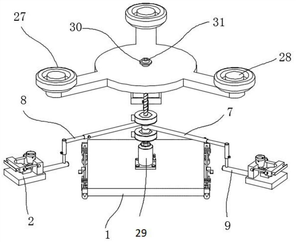
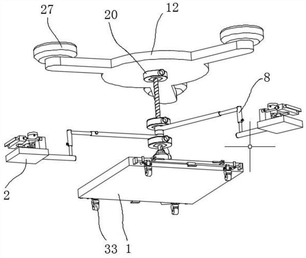
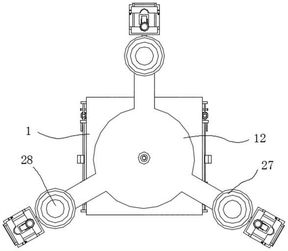
[0029] refer to Figure 1 to Figure 11 The shown installation equipment for piano casters includes a base 1, a lifting mechanism, a workpiece clamping assembly, an adjustment assembly, a locking assembly and a pressing assembly. The lifting mechanism is vertically arranged on the top of the base 1, and the workpiece is clamped The assembly includes a first support block 2, a first fixing plate 3, a compression strip 4 and a fixer. The first support block 2 is fixedly connected to one end of the adjustment assembly. The first fixing plate 3 is arranged on the top of the first support block 2 and fixed connection, the compression bar 4 is arranged above the first support block 2, the first fixing plate 3 is provided with a first notch 5 in the shape of an arc, and the compression bar 4 is provided with a second notch 6 in the shape of an arc , the inner side of the first notch 5 and the second notch 6 fit the outer side of the connecting part of the piano caster, the fixer is arranged on the outer side of the pressing bar 4, the adjustment assembly includes the first support rod 7, the second support rod 8 and the first Three support rods 9, the first support rod 7 is sleeved on the lifting mechanism, the inner side of the first support rod 7 is provided with a first sliding groove 10 for accommodating the second support rod 8, the second support rod 8 is L-shaped and the second The horizontal end of support rod 8 is inserted in the first slide groove 10, the vertical end of second support rod 8 is provided with second slide groove 11, the 3rd support rod 9 is L shape and the vertical of the 3rd support rod 9 The end is inserted in the second sliding groove 11, the horizontal end of the third support rod 9 is fixedly connected with the first support block 2, the locking assembly includes a locker and a rotating mechanism, the locker is sleeved on the lifting mechanism, and rotates The mechanism is arranged on the outside of the locking device, and the compression assembly includes a support platform 12 and a rubber compression device, the support platform 12 is sleeved on the lifting mechanism, and the compression device is arranged on the top of the support platform 12 .
[0030] The workpiece clamping assembly also includes a second support block 13, a limit plate 14 and two guide rods 15, the second support block 13 is arranged on the top of the first support block 2, and the two guide rods 15 are horizontally arranged on the second Above a support block 2, one end of each guide rod 15 is fixedly connected with the first fixed plate 3, the other end of the guide rod 15 runs through the compression strip 4 and the extension end is fixedly connected with the limit plate 14, and the second support block The top of 13 is provided with the arc groove 16 that accommodates for piano caster, and anchor is bolt and nut. When in use, the piano casters are placed on the second supporting block 13, and the connecting portion on the piano casters is placed at the second notch 6 on the first fixed plate 3, and the outer wall of the connecting portion of the piano casters fits with the second notch 6, Push the compression strip 4 to the first fixed plate 3 through the guide rod 15, and when the first notch 5 fits with the outer wall of the connecting part of the piano caster, the compression strip 4 and the first The fixed plate 3 is connected. When the piano casters are taken out, the bolts are loosened, and the compression strip 4 is slid through the guide rod 15 so as to be far away from the first fixed plate 3. The compression strip 4 cannot be separated from the guide rod 15 through the limit plate 14 , the lifting mechanism is provided with three adjustment components and workpiece clamping components, and they are superimposed on each other. There are three locking components with the same structure. One of the locking components is located at the bottom of the support table 12, and the other two locking components are respectively Located on the top of the first adjustment component and the bottom of the last adjustment component.
[0031] The first support rod 7 and the second support rod 8 are respectively provided with an adjustment locker 17 . When the lifting mechanism is raised to an appropriate height, the workpiece clamping assembly will deviate from the supporting legs of the piano, the first supporting rod 7 needs to adjust the distance between the workpiece clamping assembly and the piano supporting legs, and the second supporting rod 8 needs to adjust the workpiece clamping assembly And the height of the piano support legs, by adjusting the distance and height, accurately position the piano casters and piano support legs.
[0032] The locking device is a hexagonal nut 18, the rotating mechanism includes an inner fixed ring 19, a one-way ratchet 20 and two fixed covers 21, the one-way ratchet 20 includes a ratchet ring 22, latch teeth 23 and a torsion spring 24, and the inner fixed ring 19 is arranged on the outside of the hex nut 18 and the inner wall of the inner fixing ring 19 is engaged with the hex nut 18, the ratchet ring 22 is arranged on the outside of the inner fixing ring 19, the ratchet ring 22 fits with the inner fixing ring 19, and the inner fixing ring The outer wall of 19 is provided with the draw-in groove 25 that accommodates latch 23, and latch 23 is arranged in the draw-in groove 25, and the outer wall of latch 23 coincides with the outer wall of inner fixing ring 19, and torsion spring 24 is arranged on the inner side of latch 23. When the support table 12 and the first support rod 7 are adjusted to a suitable height on the lifting mechanism, the support table 12 and the first support rod 7 are fixed by the hex nut 18 and the rotating mechanism. Usually, it is cumbersome to turn the hex nut 18 manually. And the efficiency is low, when the one-way ratchet 20 is used, the work efficiency is effectively improved, and time and effort are saved.
[0033] The two fixing covers 21 are fixedly connected to the top and the bottom of the ratchet ring 22 and the inner fixing ring 19 respectively, and an insertion hole 26 is arranged on the outer wall of the ratchet ring 22 . Insert a cylindrical tool such as a crowbar or a steel pipe into the socket 26, and quickly fix the supporting platform 12 and the three first supporting rods 7 through the principle of the one-way ratchet 20.
[0034] Described compactor is three suction cups 27, and the bottom of each suction cup 27 is all provided with a threaded hole for bolt to pass through, and the top of support table 12 is provided with three threaded holes and is facing the threaded hole of each suction cup 27, A bolt is arranged inside each suction cup 27 , and a rubber pad 28 is arranged on the top of the bolt. When the lifting mechanism rises, it drives the supporting platform 12 to rise, thereby driving the three suction cups 27 until the three suction cups 27 withstand the bottom of the piano. When the three suction cups 27 resist, the rubber pad 28 effectively prevents the bolt from colliding with the bottom of the piano.
[0035] Described elevating mechanism is jack 29, and the top of support platform 12 is provided with support platform limit mechanism, and support platform limit mechanism comprises gasket 30 and two limit nuts 31, and gasket 30 is arranged on two limit nuts. 31, two limit nuts 31 are arranged on the top of the support platform 12 and are movably connected. The support platform 12 and the locking assembly are compressed by the support platform limiting mechanism, so that the support platform 12 cannot shake.
[0036] Both sides of described base 1 are provided with a pulley assembly respectively, and pulley assembly comprises pulley support bar 32, positioning mechanism and two universal wheels 33, and the two ends of pulley support bar 32 are respectively provided with a third supporting block 34, the first The three support blocks 34 are all fixedly connected with the base 1, and the two universal wheels 33 are arranged on the pulley support bar 32 and are hinged. It is inconvenient to move the whole device, but it is very convenient to move the whole device through the universal wheel 33 at the bottom of the base 1 and the working efficiency is improved.
[0037] The positioning mechanism includes a rotatable first moving block 35 and a rotatable second moving block 36, the first moving block 35 is arranged in a horizontal state and one end is provided with a fourth support rod 37, the first moving block 35 and the fourth The support rod 37 is hinged, and the two ends of the fourth support rod 37 are respectively provided with a fourth support block 38, and the second moving block 36 is arranged in a vertical state and is provided with a fifth support rod 39 near the base 1 side. The rod 39 is hinged to the second moving block 36 , and the fifth support rod 39 is fixedly connected to the base 1 . When the equipment is moved to an appropriate position, the universal wheel 33 is lifted by the pulley support rod 32, rotated by the fourth support block 38 after lifting, adjusted to the outside of the universal wheel 33, and then the fourth support rod 37 is used to lift the universal wheel 33 Four support blocks 38 block, and allow universal wheel 33 can not rotate on pulley support bar 32.
[0038] The pulley support bar 32 is provided with an overturning plate 40 , and the overturning plate 40 is fixedly connected with the pulley support bar 32 . It is very convenient to lift or put down the universal wheel 33 through the turning board 40 .
[0039] Working principle: when in use, put the piano casters on the second support block 13, the connecting part on the piano casters is placed at the second notch 6 on the first fixed plate 3, the outer wall of the connecting part of the piano casters and the second notch 6 Fitting, push the compression strip 4 to the first fixed plate 3 through the guide rod 15, when the first notch 5 is attached to the outer wall of the connection part of the piano caster, the compression strip 4 will be pushed through the threaded cooperation of the bolt and the nut. Connect with the first fixed plate 3, when taking out the piano casters, loosen the bolts, slide the compression bar 4 through the guide rod 15, so as to stay away from the first fixed plate 3, and make the compression bar 4 unable to disengage through the limit plate 14 Guide rod 15, three adjustment components and workpiece clamping components are set on the lifting mechanism, and they are superimposed on each other. There are three locking components with the same structure. One of the locking components is located at the bottom of the support table 12, and the other two lock The tightening components are respectively located on the top of the first adjusting component and the bottom of the last adjusting component. When the lifting mechanism rises to an appropriate height, the workpiece clamping component will deviate from the supporting legs of the piano. The first supporting rod 7 needs to adjust the workpiece clamping The distance between the components and the piano support legs, the second support rod 8 needs to adjust the height of the workpiece clamping assembly and the piano support legs, by adjusting the distance and height, the piano casters and the piano support legs are accurately positioned, the support platform 12 and the first When the support bar 7 is adjusted to a suitable height on the lifting mechanism, the support table 12 and the first support bar 7 are fixed by the hexagonal nut 18 and the rotating mechanism. Usually, the manual rotation of the hexagonal nut 18 is cumbersome and inefficient. The one-way ratchet 20 effectively improves the work efficiency, and saves time and effort. Insert a cylindrical tool such as a crowbar or a steel pipe into the socket 26, and use the principle of the one-way ratchet 20 to quickly move the support table 12 and the three thirds. A support rod 7 is fixed, and when the lifting mechanism rises, it drives the support platform 12 to rise, thereby driving the three suction cups 27 until the three suction cups 27 withstand the bottom of the piano. When the three suction cups 27 resist, the rubber pad 28 effectively prevents the The bolt collides with the bottom of the piano, and the support platform 12 and the locking assembly are pressed tightly by the support platform limit mechanism, so that the support platform 12 cannot shake, and it is very inconvenient to move the whole device. The whole device is very convenient and improves work efficiency. When the device is moved to an appropriate position, the universal wheel 33 is lifted by the pulley support rod 32, and after lifting, it is rotated by the fourth support block 38 and adjusted to the outside of the universal wheel 33 , then the fourth support block 38 is blocked by the fourth support bar 37, so that the universal wheel 33 can not rotate on the pulley support bar 32, and it is very convenient to lift or put down the universal wheel 33 by the flip plate 40.
[0040] The above description is only an embodiment of the present invention, and is not intended to limit the present invention. Various modifications and variations of the present invention will occur to those skilled in the art. Any modification, equivalent replacement, improvement, etc. made within the spirit and principle of the present invention shall be included in the scope of the claims of the present invention.

PUM

no PUM

Description & Claims & Application Information

We can also present the details of the Description, Claims and Application information to help users get a comprehensive understanding of the technical details of the patent, such as background art, summary of invention, brief description of drawings, description of embodiments, and other original content. On the other hand, users can also determine the specific scope of protection of the technology through the list of claims; as well as understand the changes in the life cycle of the technology with the presentation of the patent timeline. Login to view more.
Why Eureka
Try Eureka