Switching circuits and electronic equipment

A technology of switching circuits and switching tubes, which is applied in the field of circuits, and can solve problems such as complex implementation methods of automatic turn-on and turn-off control

Active Publication Date: 2019-02-15
天津航空机电有限公司
View PDF6 Cites 3 Cited by
  • Summary
  • Abstract
  • Description
  • Claims
  • Application Information

AI Technical Summary

Problems solved by technology

[0004] Embodiments of the present invention provide a switch circuit and electronic equipment to overcome the problem of complex implementation methods of automatic turn-on and turn-off control of existing switch circuits or electronic equipment without manual intervention

Method used


Image

  • Switching circuits and electronic equipment
  • Switching circuits and electronic equipment
  • Switching circuits and electronic equipment

Examples


Embodiment 1

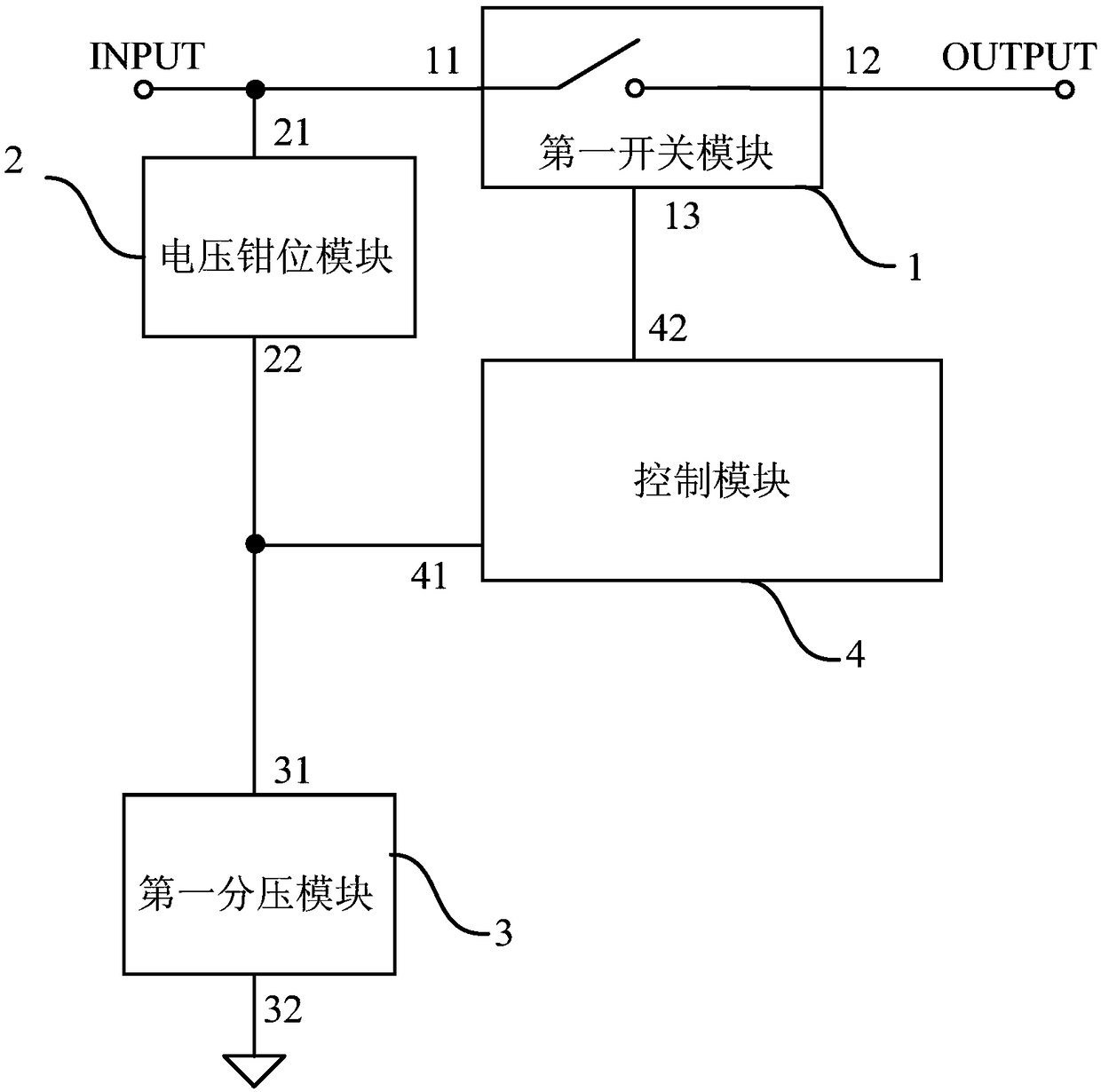
[0049] An embodiment of the present invention provides a switch circuit. figure 1 It is a schematic structural diagram of a switch circuit provided by Embodiment 1 of the present invention. This embodiment is applicable to the case where the switch circuit controls the switching on and off of the power supply and the main power circuit where the load is located. see figure 1 A switch circuit provided by the implementation of the present invention includes: a first switch module 1 , a voltage clamp module 2 , a first voltage divider module 3 and a control module 4 .

[0050] Wherein, the first terminal 11 of the first switch module 1 is electrically connected to the first terminal INPUT of the switch circuit, the second terminal 12 of the first switch module 1 is electrically connected to the second terminal OUTPUT of the switch circuit, and the voltage clamping module 2 The first end 21 is electrically connected to the first end INPUT of the switch circuit, the first end 31 ...

Embodiment 2

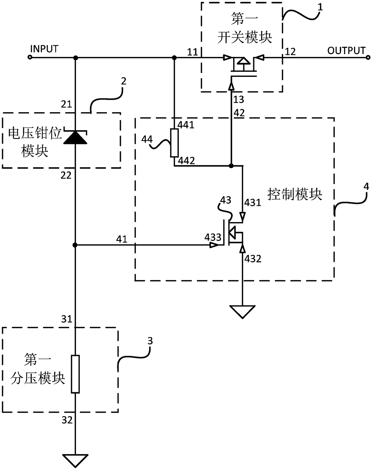
[0055] An embodiment of the present invention provides yet another switch circuit. figure 2 It is a schematic structural diagram of a switch circuit provided in Embodiment 2 of the present invention. On the basis of the above examples, see figure 2 , the control module 4 includes a first switch tube 43 and a fifth resistor 44, the first terminal 441 of the fifth resistor 44 is electrically connected to the first terminal INPUT of the switch circuit, and the second terminal 442 of the fifth resistor 44 is connected to the first switch tube The first end 431 of the first switch tube 43 is electrically connected, the second end 432 of the first switch tube 43 is grounded, the control terminal 433 of the first switch tube 43 is electrically connected to the input terminal 41 of the control module 4, and the first end of the first switch tube 43 431 is electrically connected to the output terminal 42 of the control module 4 .

[0056] Wherein, the first switch tube 43 may be a ...

Embodiment 3

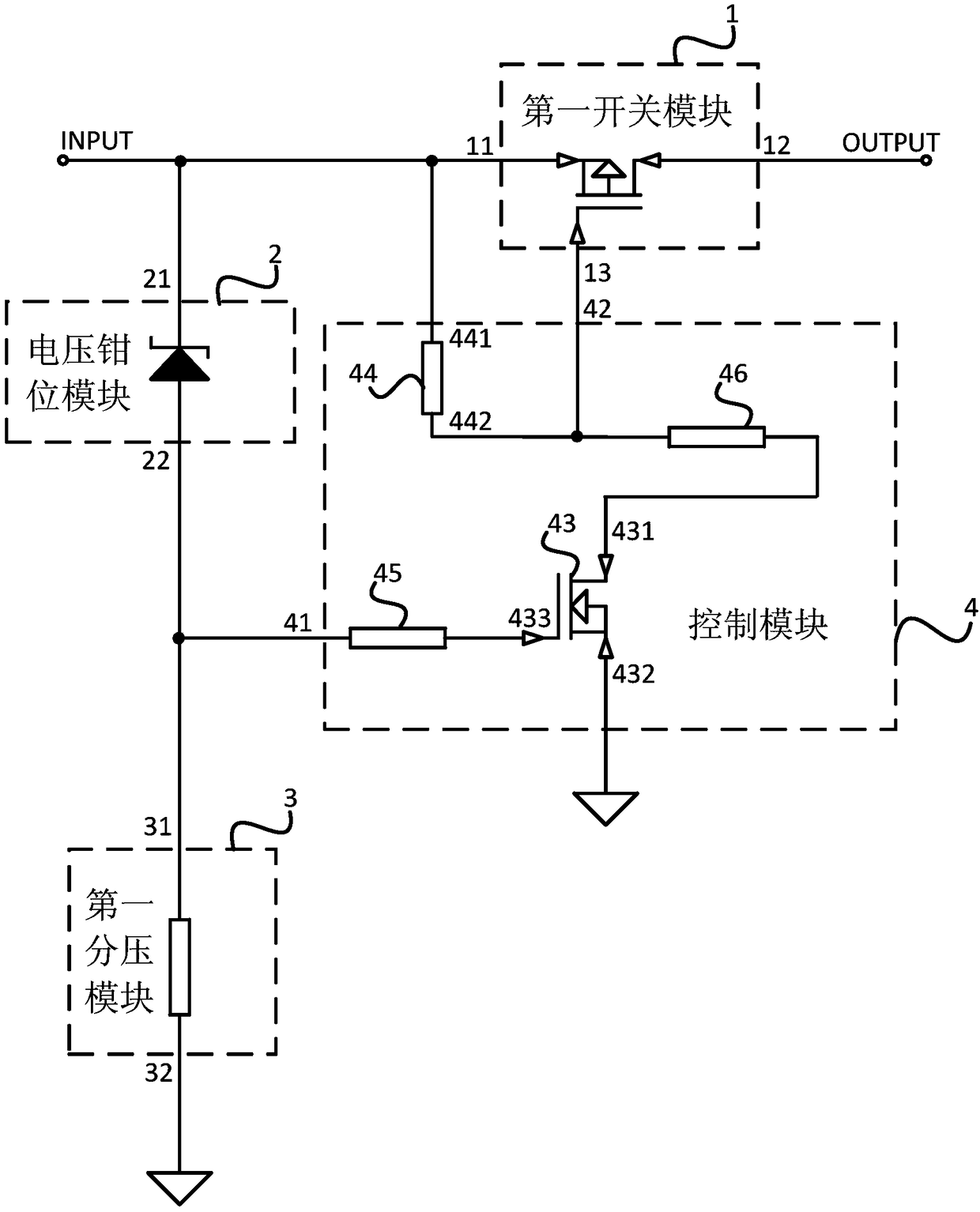
[0058] An embodiment of the present invention provides yet another switch circuit. image 3 It is a schematic structural diagram of a switch circuit provided by Embodiment 3 of the present invention. Based on the above embodiments, the control module 4 further includes a sixth resistor 45 , and the control terminal 433 of the first switch tube 43 is electrically connected to the input terminal 41 of the control module 4 through the sixth resistor 45 . The sixth resistor 45 acts as a current limiter. Optionally, continue to see image 3 , the control module 4 also includes a seventh resistor 46, the first end 431 of the first switch tube 43 is electrically connected to the control end 13 of the first switch module 1 through the seventh resistor 46, and the second end 442 of the fifth resistor 44 is connected through the second end 442 The seven resistors 46 are electrically connected to the first end 431 of the first switch tube 43 , and the seventh resistor 46 acts as a volt...


PUM


Abstract

The embodiments of the invention disclose switching circuits and electronic equipment. a switching circuit comprises a first switch module, wherein a first end of the first switch module is electrically connected with the first end of the switching circuit, and a second end of the first switch module is electrically connected with the second end of the switching circuit; a voltage clamp module, wherein the first end of the voltage clamp module is electrically connected with the first end of the switching circuit; a first voltage division module, wherein the first end of the first voltage division module is electrically connected with the second end of the voltage clamp module, and the second end of the first voltage division module is grounded; and a control module, wherein an input end ofthe control module is electrically connected with the first end of the first voltage division module, and an output end of the control module is electrically connected with a control end of the firstswitch module. According to the technical scheme provided by the invention, a main power circuit automatic switch-off and switch-on control function can be realized, an auxiliary source is avoided, and the switching circuits and the electronic equipment are characterized by high economical efficiency and high reliability.

Description

technical field [0001] The embodiments of the present invention relate to the technical field of circuits, and in particular to a switch circuit and electronic equipment. Background technique [0002] When the battery is powered or the DC power supply is used, it is necessary to cut off the connection between the load and the power supply when the battery discharge ends or the DC power supply voltage is lower than a certain limit to protect the battery or the DC power supply. Especially when the battery is used as the power supply, if the connection between the load and the power supply is not cut off in time, the battery will be damaged due to over-discharge and the service life of the battery will be reduced. After the battery is recharged or the supply voltage of the DC power supply meets the requirements, it is necessary to restore the connection between the load and the power supply to ensure the normal power supply requirements. [0003] However, the existing switch f...

Claims


Application Information

Patent Timeline
Patent Type & Authority Applications(China)
IPC IPC(8): H03K17/56H02H7/18
CPCH02H7/18H03K17/56
Inventor 林引胜席朝飞臧思田
Owner 天津航空机电有限公司
Why Eureka
Try Eureka