Auxiliary device and method for engine gear tightening

An auxiliary device and engine technology, which is applied in metal processing, metal processing equipment, manufacturing tools, etc., can solve the problems that the bolt torque cannot be guaranteed, the quality of the engine is affected, and the crowbar is easy to hurt people, etc., so as to improve assembly efficiency and production safety High performance, compact structure and wide application range

Pending Publication Date: 2019-02-19
GUANGXI YUCHAI MASCH CO LTD
View PDF7 Cites 1 Cited by
  • Summary
  • Abstract
  • Description
  • Claims
  • Application Information

AI Technical Summary

Problems solved by technology

[0002] During the assembly process of the engine, it is necessary to tighten multiple gears of the end face gear train on the body. In the actual assembly process, when the fastening bolts of the gears are tightened with a torque wrench, the gear train will rotate and the torque of the bolts cannot be guaranteed. If the torque of the engine gear fastening bolts is not enough, after the engine runs at high speed for a long time, it may cause faults such as gear flying out, which will seriously affect the quality of the engine
At present, the method to prevent the gear train from rotating is to directly use a crowbar to block the meshing part of the gears so that the gears cannot rotate so as to prevent the gear train from rotating
However, during the tightening process, the crowbar may fall off from time to time, and the effect of preventing follow-up rotation is not good, and the crowbar may easily hurt people when the crowbar falls off, which has potential safety hazards. damage problem

Method used


Image

  • Auxiliary device and method for engine gear tightening
  • Auxiliary device and method for engine gear tightening
  • Auxiliary device and method for engine gear tightening

Examples


Embodiment 1

[0026] refer to Figure 4-5 , is a specific embodiment of the present invention. In this embodiment, its clamping assembly is slidably installed on the fixed plate 1 through a sliding assembly. The sliding assembly includes a guide rail 9 arranged on the fixed plate 1 and a connecting block 4 The slider 10 is slidingly connected with the guide rail 9, and the clamping assembly is set to a slidable form, and the position of the clamping block 5 can be adjusted appropriately so that the clamping block 5 can be completely engaged with the timing gear 17, thereby To achieve the purpose of protecting the gears from damage, since the snap-in assembly is movable, an adjustment assembly for adjusting the displacement of the snap-in assembly is also provided on the fixed plate 1. The adjustment assembly includes a turntable 11, a screw rod 12, and a support seat 13 , the support base 13 is installed on the fixed plate 1, the screw 12 is installed on the support base 13 through the bear...

Embodiment 2

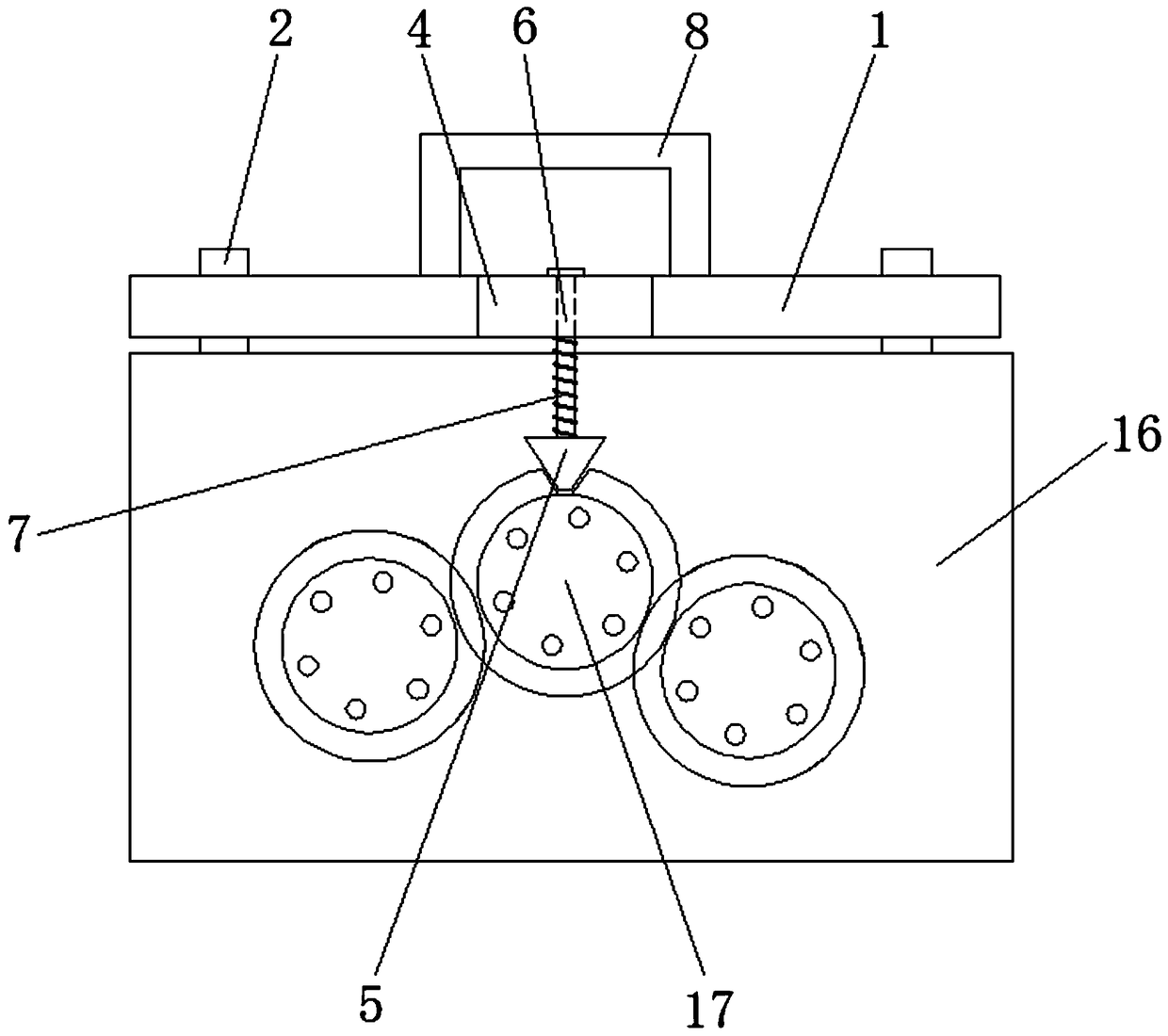
[0028] refer to Figure 6-7 , is another specific embodiment of the present invention, this embodiment is basically the same as Embodiment 1, the difference is that a side positioning plate 14 that is hingedly connected to it is also provided on one side of the fixing plate 1, and the side positioning plate 14 can be Rotate relative to the fixed plate 1, a detachable auxiliary pin 15 is provided at one end of the side positioning plate 14, and the side positioning plate 14 is arranged on the same side as the clamping assembly, the auxiliary pin 15 is used to match with the front hole of the body 16, when fixed When the positioning pin 2 on the board 1 cannot complete the positioning, the clamping assembly can be positioned by using the auxiliary pin 15 to cooperate with the positioning pin 2, which expands the scope of application of the auxiliary device.


PUM


Abstract

The invention discloses an auxiliary device for engine gear tightening. The auxiliary device comprises a fixed plate and at least two positioning pins, wherein a plurality of pin holes are axially formed in the fixed plate, the positioning pins are movably inserted into the pin holes, a clamping assembly which is bulged to one side of the fixed plate is arranged in the middle of the fixed plate, the clamping assembly comprises a connecting block which is connected with the fixed plate, a clamping block which can be inserted into a gear groove of a gear and a connecting rod which is used for connecting the clamping block with the connecting block, the connecting rod is movably inserted into the connecting block, and a spring sleeves the connecting rod between the connecting block and the clamping block. According to the auxiliary device, the problem of rotation of the gear and the problem of damage to the gear can be effectively prevented. The invention further discloses an engine geartightening method. A motor gear system can be quickly tightened by using the method, so that the assembly efficiency and the production safety are increased, and the labor intensity is reduced.

Description

technical field [0001] The invention relates to the technical field of engine gear assembly, more specifically, it relates to an auxiliary device and method for tightening engine gears. Background technique [0002] During the assembly process of the engine, it is necessary to tighten multiple gears of the end face gear train on the body. In the actual assembly process, when the fastening bolts of the gears are tightened with a torque wrench, the gear train will rotate and the torque of the bolts cannot be guaranteed. If the torque of the engine gear fastening bolts is not enough, after the engine runs at high speed for a long time, it may cause faults such as gear flying out, which will seriously affect the quality of the engine. At present, the method to prevent the gear train from co-rotating is to directly block the meshing part of the gears with a crowbar, so that the gears cannot rotate so as to prevent the gear train from co-rotating. However, during the tightening p...

Claims


Application Information

Patent Timeline
Patent Type & Authority Applications(China)
IPC IPC(8): B23P19/00B23P19/06
CPCB23P19/00B23P19/06
Inventor 梁秉泉李诗彬王东波梁敏
Owner GUANGXI YUCHAI MASCH CO LTD
Why Eureka
Try Eureka