Electric conducting roller capable of reducing arcing phenomenon in electrode foil powerup process

An electrode foil and conductive roller technology, applied in the field of conduction, can solve the problems of reducing product quality, waste, deformation of aluminum foil, etc., and achieve the effects of reducing flashover problems, enhancing current-carrying capacity, and reducing heat generation.

Inactive Publication Date: 2019-02-19
YANGZHOU HONGYUAN ELECTRONICS
View PDF0 Cites 2 Cited by
  • Summary
  • Abstract
  • Description
  • Claims
  • Application Information

AI Technical Summary

Problems solved by technology

At present, the general practice is to directly contact the aluminum foil with a smooth conductive roller to conduct the current to the aluminum foil. With the continuous increase in production speed, the current applied to the conductive roller continues to increase. The contact area with the aluminum foil is limited, the conductive effect is not ideal, the heat generated by the contact part of the conductive roller and the aluminum foil is getting larger and larger, and flashover often occurs, and the aluminum foil is easy to deform and wrinkle after being heated, which reduces the product quality. prone to large waste
To solve this problem, the effect is still not ideal by adding an air cooling device or passing cooling water inside the conductive roller, and at the same time it will bring a series of other problems, such as uneven heat dissipation, impurities in the air pollute the surface of the aluminum foil, conductive The surface of the roller is prone to condensate, etc.

Method used


Image

  • Electric conducting roller capable of reducing arcing phenomenon in electrode foil powerup process
  • Electric conducting roller capable of reducing arcing phenomenon in electrode foil powerup process
  • Electric conducting roller capable of reducing arcing phenomenon in electrode foil powerup process

Examples


Embodiment Construction

[0012] Below in conjunction with accompanying drawing and specific embodiment, further illustrate the present invention, it should be understood that these embodiments are only used to illustrate the present invention and are not intended to limit the scope of the present invention, after reading the present invention, those skilled in the art will understand various aspects of the present invention Modifications in equivalent forms all fall within the scope defined by the appended claims of this application.

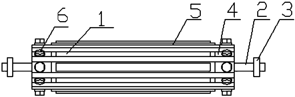
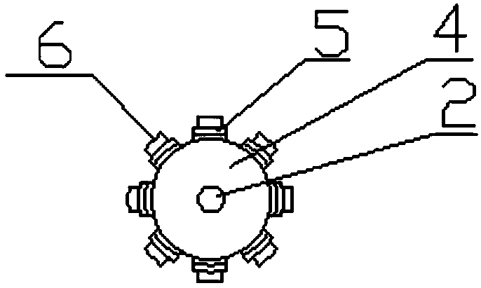
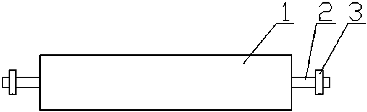
[0013] Such as figure 1 As shown: the present invention provides a conductive roller that reduces the flashover phenomenon during the electrification process of the electrode foil. The specific technical solution includes a cylinder body 1 and a roller shaft 2 running through it, and bearings are installed at both ends of the roller shaft 2 3. The left and right ends of the cylinder 1 are respectively equipped with circular end caps 4, the roller shaft 2 passes through ...


PUM


Abstract

The invention provides an electric conducting roller capable of reducing the arcing phenomenon in an electrode foil powerup process. The electric conducting roller comprises a cylinder, and a roller shaft penetrating in the cylinder; bearings are mounted at two ends of the roller shaft; circular end covers are additionally mounted at the left and right ends of the cylinder; the roller shaft penetrates through the centers of the end covers; and an electric conducting bar is fixedly arranged in the axial direction of the outer surface of the cylinder. In the electric conducting roller capable ofreducing the arcing phenomenon in the electrode foil powerup process, through adding of the electric conducting bar on the surface of the cylinder, the current carrying capacity is improved, the heating quantity is reduced, the defect caused by adding of a cooling device is prevented, and the arcing problem in the electrode foil powerup process is reduced.

Description

technical field [0001] The invention belongs to the field of electric conduction technology, and in particular relates to a conduction roller for reducing flashover phenomenon during electrification of electrode foils. Background technique [0002] The electrode foil for aluminum electrolytic capacitors often uses electrolytic technology in the production process (corrosion, chemical conversion process), that is, by applying direct or alternating current to the aluminum foil to perform electrolytic corrosion and drilling in the chemical solution, and then form an oxide film on the surface of the electrode foil. At present, the general practice is to directly contact the aluminum foil with a smooth conductive roller to conduct the current to the aluminum foil. With the continuous increase in production speed, the current applied to the conductive roller continues to increase. The contact area with the aluminum foil is limited, the conductive effect is not ideal, the heat gene...

Claims


Application Information

Patent Timeline
Patent Type & Authority Applications(China)
IPC IPC(8): C25F7/00C25F3/04
CPCC25F7/00C25F3/04
Inventor 吉民马坤松乔正山相志明张栓
Owner YANGZHOU HONGYUAN ELECTRONICS
Why Eureka
Try Eureka