Rubber hose and manufacturing method

A rubber tube and natural rubber technology, applied in the direction of hoses, pipes, flange connections, etc., can solve the problems of pipelines that cannot meet the requirements of seismic isolation, large deformation of pipelines, low reaction force, etc., and achieve repeated deformation fatigue Excellent, strong deformation ability, low reaction force effect

Pending Publication Date: 2019-02-19
CHINA INST OF BUILDING STANDARD DESIGN & RES
View PDF0 Cites 3 Cited by
  • Summary
  • Abstract
  • Description
  • Claims
  • Application Information

AI Technical Summary

Problems solved by technology

[0003] The purpose of the present invention is to provide a rubber tube and its production method, to solve the technical problem that the existing pip

Method used


Image

  • Rubber hose and manufacturing method
  • Rubber hose and manufacturing method

Examples


Embodiment Construction

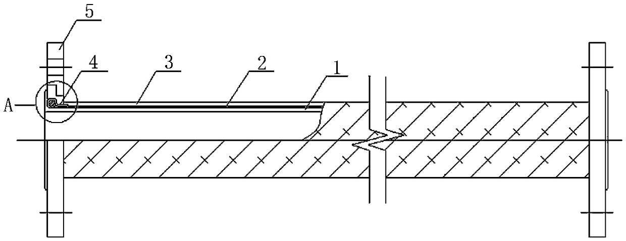
[0031] Examples see figure 1 As shown, this kind of rubber tube includes a hose segment and flanges 5 arranged at both ends of the hose segment. The tube wall of the hose segment includes an inner rubber layer 1, a reinforcing layer 2 and an outer Adhesive layer 3 ; the end of the reinforcement layer 2 is wound around the limiting ring 4 and embedded in the tongue and groove of the flange 5 . The flange shown is a movable movable flange, the inner ring is stepped, and a tenon groove is formed on the step surface. The hole diameter and hole position are in accordance with the requirements of the flange national standard, and the material is Q235 steel.

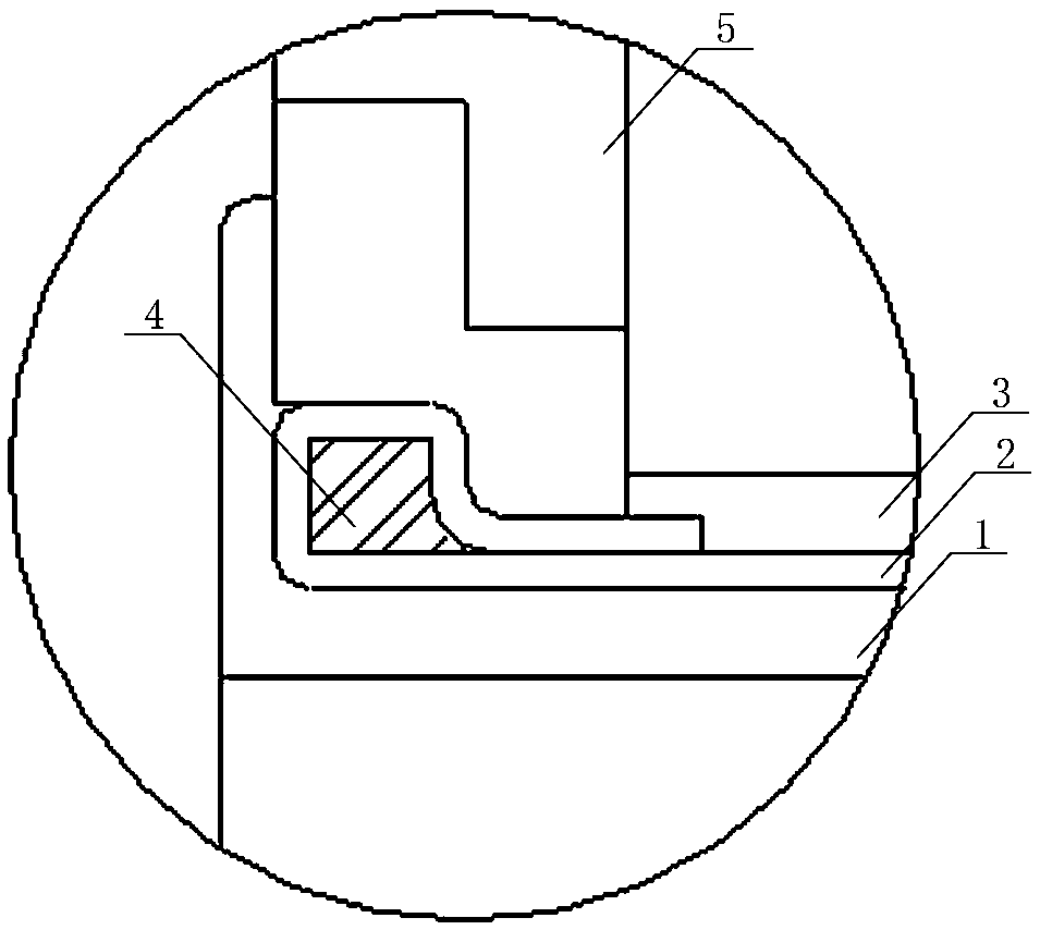
[0032] see figure 2 As shown, the end of the inner rubber layer 1 passes through the flange and is horizontally folded outward to cover the outer end surface of the flange, and the length exceeds the tongue and groove position of the flange.

[0033] The end of the reinforcing layer 2 is folded outwards at 180 degrees, and f...


PUM


Abstract

The invention discloses a rubber hose and a manufacturing method thereof. The rubber hose comprises a hose section and flange plates arranged at two ends of the hose section, wherein the hose wall ofthe hose section comprises an inner rubber layer, a strengthening layer and an outer rubber layer, which are arranged sequentially from inside out; and ends of the strengthening layer are wound aroundspacing rings and embedded and fixed in mortises of the flange plates. According to the rubber hose provided by the invention, the inner rubber layer contacts an in-pipeline medium and ends of the inner rubber layer turn back to enclose the flange plates to be used for sealing; the strengthening layer performs a function of pressure bearing; the outer rubber layer plays a protective role; the flange plates are used for connection; and the spacing rings and the flange plates jointly fix the strengthening layer, so as to prevent the relative displacement between the strengthening layer and rubber during a deformation process, which can affect the capacity of pressure bearing. The rubber hose referred to in the invention is applied to the flexible connection of important pipelines passing through a seismic isolation layer, so as to protect the important equipment pipelines from damage during a deformation occurring in an earthquake; the rubber hose has the characteristics of strong deformation capacity with a maximum being up to +/-700 mm, small reaction force and good durability; and besides, the fatigue resistance for repeated deformation is excellent and the service life is long.

Description

technical field [0001] The invention relates to the technical field of building earthquake isolation, in particular to a pipeline structure in an earthquake isolation layer and a manufacturing method thereof. Background technique [0002] Building isolation technology is a new anti-seismic technology, which can effectively improve the anti-seismic ability of buildings. Building isolation technology is mainly to use isolation bearings in the isolation layer to reduce the damage of earthquakes to buildings, and isolation bearings have been widely used. However, the treatment of pipes, pipelines and other connecting parts passing through the isolation layer is generally poor, and the damage of important equipment and pipelines in the earthquake cannot be avoided, and the continuity of building functions after the earthquake cannot be guaranteed. Existing pressure-bearing rubber hoses are usually required to be non-deformable or difficult to deform, which does not meet the requ...

Claims


Application Information

Patent Timeline
IPC IPC(8): F16L11/10F16L23/024B29C69/00
CPCF16L11/10B29C69/00B29L2023/22F16L23/024
Inventor 邓烜王宽叶烈伟雷远德王伟凤李进波
Owner CHINA INST OF BUILDING STANDARD DESIGN & RES
Why Eureka
Try Eureka