[0033] In order to facilitate the understanding of the present invention, the present invention will be described more fully below with reference to the relevant drawings. The preferred embodiments of the invention are shown in the drawings. However, the present invention can be implemented in many different forms and is not limited to the embodiments described herein. On the contrary, the purpose of providing these embodiments is to make the understanding of the disclosure of the present invention more thorough and comprehensive.
[0034] Unless otherwise defined, all technical and scientific terms used herein have the same meaning as commonly understood by those skilled in the technical field of the present invention. The terminology used in the specification of the present invention herein is only for the purpose of describing specific embodiments, and is not intended to limit the present invention. The term "and/or" as used herein includes any and all combinations of one or more of the related listed items.
[0035] Due to the temperature rise of the battery pack at low temperatures, and the capacity of the battery cell after forming the PACK is affected by the barrel effect of the consistency of the battery cell, the capacity data of the single battery cell cannot be directly converted into the capacity of the entire battery pack, so There is no way to get the accurate value of battery pack capacity data by directly testing the capacity.
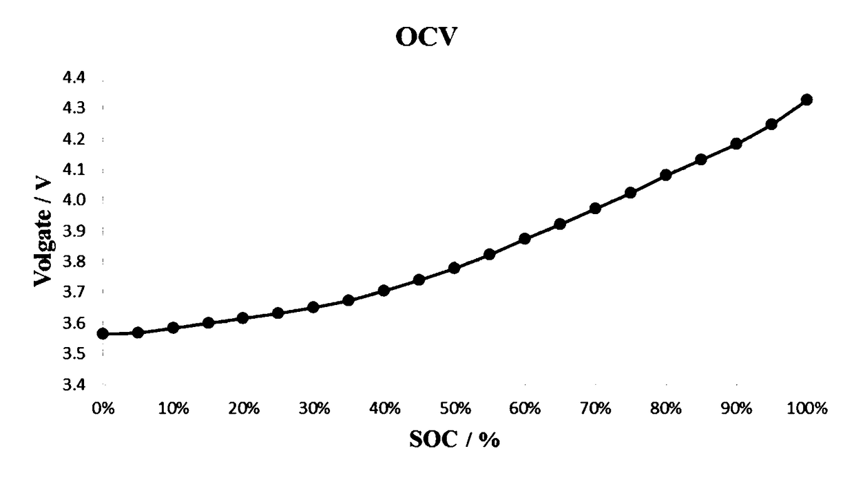
[0036] There is a battery management system in the battery pack to monitor each string of single cells inside the battery pack, so although the battery pack capacity value cannot be visually observed, the battery pack can read the open circuit voltage value of the single cells by using the cells SOC (state of charge)-OCV (open circuit voltage) data of different temperatures tested. figure 1 It shows the SOC-OCV curve of a battery cell at a temperature. Table 1 is a SOC-OCV table obtained by taking the values of the SOC-OCV curve of a battery cell at different temperatures.
[0037] Table 1
[0038]
[0039] The present invention uses the SOC (state of charge)-OCV (open circuit voltage) curve to determine the capacity data at the target temperature.
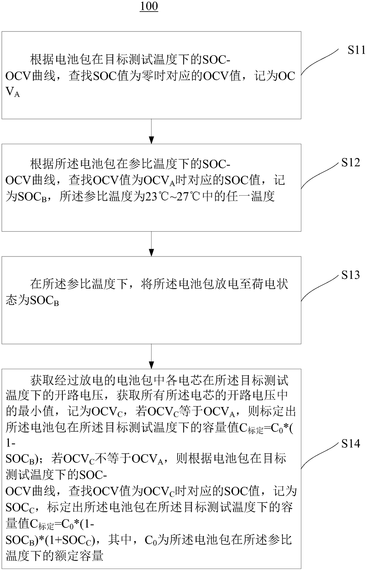
[0040] Such as figure 2 As shown, a method 10 for calibrating battery pack capacity data according to an embodiment of the present invention includes the following steps:
[0041] Step S11, according to the SOC (state of charge)-OCV (open circuit voltage) curve of the battery pack at the target test temperature, find the OCV value corresponding to the zero SOC value, and record it as OCV A;
[0042] Step S12, according to the SOC-OCV curve of the battery pack at the reference temperature, find the OCV value OCV A The corresponding SOC value at time, denoted as SOC B , The reference temperature is any temperature between 23℃~27℃;
[0043] Step S13, at the reference temperature, discharge the battery pack until the state of charge is SOC B;
[0044] Step S14: Obtain the open circuit voltage of each cell in the discharged battery pack at the target test temperature, and obtain the minimum value of the open circuit voltage of all cells, which is recorded as OCV C , If OCV C Equal to OCV A , The capacity value C of the battery pack at the target test temperature is calibrated Calibration =C 0 *(1-SOC B ); if OCV C Not equal to OCV A , According to the SOC-OCV curve of the battery pack at the target test temperature, find the OCV value OCV C The corresponding SOC value at time, denoted as SOC C , Calibrate the capacity value C of the battery pack at the target test temperature Calibration =C 0 *(1-SOC B )*(1+SOC C ), where C 0 It is the rated capacity of the battery pack at the reference temperature.
[0045] The SOC-OCV curve is the characteristic curve of the battery cell, and a temperature corresponds to a SOC-OCV curve. Since each cell in the battery pack is the same, the SOC-OCV curve of each cell at the same temperature is the same. The SOC-OCV curve of the battery pack in the present invention is the SOC-OCV curve of each cell.
[0046] Please combine figure 1 , figure 2 As shown in Table 1, for example, in step S11, if the target test temperature is 0°C and the SOC value is zero, the corresponding OCV value is 3.516, that is, OCV A = 3.516. In step S12, if the reference temperature is 25°C and the OCV value is 3.516, the corresponding SOC value is 13%, that is, SOC B Is 13%. In step S13, the battery pack is placed at a reference temperature (25°C), and the battery pack is discharged to a state of charge of 13%. In step S14, the battery pack is placed at the target test temperature (0°C), and after the battery pack reaches temperature equilibrium, it is allowed to stand for 2 hours to obtain the open circuit voltage of each cell in the discharged battery pack at the target test temperature, and record The minimum value of the open circuit voltage of all cells OCV C , If OCV C Equal to OCV A (3.516), the capacity value C of the battery pack at the target test temperature is calibrated Calibration =C 0 *(1-SOC B )=87%C 0. If OCV C Not equal to OCV A , According to the SOC-OCV curve of the battery pack at the target test temperature, find the OCV value OCV C The corresponding SOC value at time, denoted as SOC C , Calibrate the capacity value C of the battery pack at the target test temperature Calibration =C 0 *(1-SOC B )*(1+SOC C ).
[0047] Preferably, the reference temperature is any temperature from 24°C to 26°C. More preferably, the reference temperature is 25°C.
[0048] In step S13, the battery pack is discharged until the state of charge is SOC B The method includes: discharging when the battery pack is fully charged, and the discharge time is t 1 =SOC B *C 0 /It, where It is the discharge rate.
[0049] In step S13, the discharge rate is preferably 1/3C to 1C. More preferably, the discharge rate is 1C.
[0050] The measurement method of the rated capacity of the battery pack at the reference temperature is as follows:
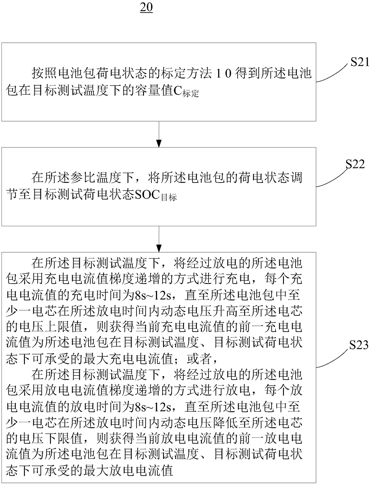
[0051] At the reference temperature, perform standard discharge on the fully charged battery pack to obtain the discharge capacity value. Please combine image 3 Further, the present invention also provides a method 20 for testing the charge and discharge capacity of a battery pack, which includes the following steps:
[0052] Step S21: Obtain the capacity value C of the battery pack at the target test temperature according to the calibration method 10 of the battery pack state of charge in any of the above examples Calibration;
[0053] Step S22, at the reference temperature, adjust the state of charge of the battery pack to the target test state of charge SOC aims;
[0054] Step S23: At the target test temperature, the discharged battery pack is charged in a manner of increasing the charging current value gradient, and the charging time for each charging current value is 8s-12s, until at least one cell in the battery pack is in the When the dynamic voltage rises to the upper limit of the battery cell voltage during the discharge time, the previous charge current value obtained from the current charge current value is the maximum charge current value that the battery pack can withstand at the target test temperature and target test state of charge; or,
[0055] At the target test temperature, the discharged battery pack is discharged using a gradient increase of the discharge current value, and the discharge time of each discharge current value is 8s-12s, until at least one cell in the battery pack is within the discharge time The dynamic voltage is reduced to the lower limit of the voltage of the battery cell, and the previous discharge current value obtained from the current discharge current value is the maximum discharge current value that the battery pack can withstand at the target test temperature and the target test state of charge.
[0056] In step S22, the state of charge of the battery pack is adjusted to the target test state of charge SOC aims The methods include:
[0057] Charge the battery pack to a fully charged state at the reference temperature, preferably using a standard charging method. Discharge the fully charged battery pack at the reference temperature, and the discharge rate is preferably 1/3C to 1C, more preferably 1C. Discharge time t 2 =C Calibration *(1-SOC aims )/C 0.
[0058] Among them, the rated capacity of the battery pack at the reference temperature can be obtained by performing standard discharge and recording the discharge value of the battery pack.
[0059] In step S23, the charging current value is gradually increased according to the gradient value of 9A to 11A; and/or, the discharging current value is increased according to the gradient value of 9A to 11A.
[0060] Hereinafter, a more specific example is used to further illustrate the method 200 for testing the charging and discharging ability of the battery pack of the present invention.
[0061] The flow of the test method is as follows:
[0062] Step 1. Adapt the battery pack to the environment at 25°C. Specifically, when the target environment temperature of the test changes, the test sample needs to complete the environmental adaptation process before the test: stand at low temperature for no less than 24h; stand at high temperature for no less than 6h; or single battery temperature and target The difference in ambient temperature should not exceed 2°C. If the test sample contains a battery control unit, it must be shut down during the environmental adaptation process.
[0063] Step 2. Perform a standard discharge on the fully charged battery pack at 25°C, and record the discharge capacity value, which is the rated capacity C of the battery pack at 25°C 0.
[0064] Step 3. Leave the battery pack to stand for 1 hour at 25°C.
[0065] Step 4. Perform a standard charge on the battery pack at 25°C.
[0066] Step 5. Leave the battery pack to stand for 1 hour at 25°C.
[0067] Step 6. According to the SOC (state of charge)-OCV (open circuit voltage) curve of the battery pack at the target test temperature, find the OCV value corresponding to the zero SOC value, and record it as OCV A.
[0068] Step 7. Find the OCV value according to the SOC-OCV curve of the battery pack at the reference temperature A The corresponding SOC value at time, denoted as SOC B.
[0069] Step 8. Discharge the battery pack at 1C at 25°C for a duration of t 1 =SOC B *C 0 /It, where It is the discharge rate.
[0070] Step 9. Change the ambient temperature to the target test temperature, and let it stand for 2 hours after the battery pack reaches temperature equilibrium.
[0071] Step 10. Obtain the open circuit voltage of each cell in the discharged battery pack at the target test temperature, and obtain the minimum value of the open circuit voltage of all cells, which is recorded as OCV C , If OCV C Equal to OCV A , The capacity value C of the battery pack at the target test temperature is calibrated Calibration =C 0 *(1-SOC B ); if OCV C Not equal to OCV A , According to the SOC-OCV curve of the battery pack at the target test temperature, find the OCV value OCV C The corresponding SOC value at time, denoted as SOC C , Calibrate the capacity value C of the battery pack at the target test temperature Calibration =C 0 *(1-SOC B )*(1+SOC C ), where C 0 It is the rated capacity of the battery pack at the reference temperature.
[0072] Step 11: Change the ambient temperature to 25°C, and adapt the battery pack to the environment at 25°C.
[0073] Step 12. Perform a standard charge on the battery pack at 25°C.
[0074] Step 13. Perform 1C discharge on the battery pack at 25°C, and the discharge time is t 2 =C Calibration *(1-SOC aims )/C 0.
[0075] Step 14. Change the ambient temperature to the target test temperature, and let it stand for 2 hours after the battery pack reaches temperature equilibrium.
[0076] Step 15. At the target test temperature, the battery pack is charged with a gradient increase of the charging current value. The gradient of the charging current value is 10A, and the charging time for each charging current value is 10s, until the battery cell opens within the charging time When the voltage value rises to the upper limit of the voltage of the battery cell, the previous charge current value obtained from the current charge current value is the maximum charge current value that the battery pack can withstand at the target test temperature and target test state of charge; or,
[0077] At the target test temperature, the battery pack is discharged with a gradient of discharge current value, the gradient of the discharge current value is 10A, and the discharge time of each discharge current value is 10s, until the open circuit voltage value of the cell decreases during the discharge time To the lower limit of the battery cell voltage, the previous discharge current value to obtain the current discharge current value is the maximum discharge current value that the battery pack can withstand at the target test temperature and the target test charge state.
[0078] The calibration method of the battery pack capacity data and the test method of charging and discharging capacity mentioned above use the SOC-OCV curve of the battery pack at the reference temperature and the target test temperature, combined with specific processing methods, to avoid direct charging and discharging at the target test temperature Capacity measurement, which can avoid temperature rise, is suitable for obtaining more accurate battery pack capacity data and charging and discharging capabilities in low temperature environments.
[0079] The technical features of the above-mentioned embodiments can be combined arbitrarily. In order to make the description concise, all possible combinations of the technical features in the above-mentioned embodiments are not described. However, as long as there is no contradiction in the combination of these technical features, All should be considered as the scope of this specification.
[0080] The above-mentioned embodiments only express several embodiments of the present invention, and the descriptions are more specific and detailed, but they should not be understood as limiting the scope of the invention patent. It should be pointed out that for those of ordinary skill in the art, without departing from the concept of the present invention, several modifications and improvements can be made, and these all fall within the protection scope of the present invention. Therefore, the protection scope of the patent of the present invention should be subject to the appended claims.