An Optimal Delay Compensation Method for Active Damping of LCL Type Converter

A delay compensation and converter technology, applied in AC network circuits, AC networks to reduce harmonics/ripples, harmonic reduction devices, etc. Phase margin or amplitude margin can not be system stability, can not achieve optimal compensation and other problems, to achieve good high-frequency harmonic suppression ability, improve stability margin, suppress the frequency shift of resonance frequency and the effect of resonance peak

Active Publication Date: 2022-05-10
NANJING UNIV OF SCI & TECH
View PDF4 Cites 0 Cited by
  • Summary
  • Abstract
  • Description
  • Claims
  • Application Information

AI Technical Summary

Problems solved by technology
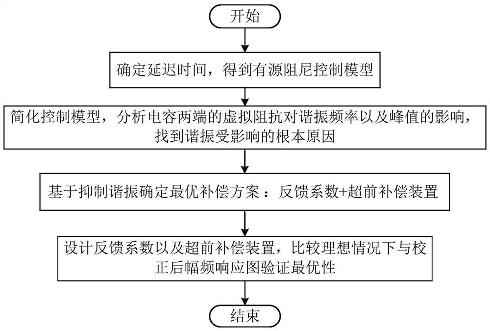
So far, the design of LCL grid-connected converters either does not consider the influence of delay on resonance, or performs delay compensation for the purpose of improving the stability margin of the system, without considering the fluctuation of resonance frequency and the increase of resonance peak And the weakening of high-frequency harmonic filtering ability, the optimal effect of delay compensation cannot be achieved
In addition, for the system after delay compensation, neither the phase margin nor the amplitude margin can be used as a scalar to determine the stability of a system, and optimal compensation cannot be achieved.

Method used


Image

  • An Optimal Delay Compensation Method for Active Damping of LCL Type Converter
  • An Optimal Delay Compensation Method for Active Damping of LCL Type Converter
  • An Optimal Delay Compensation Method for Active Damping of LCL Type Converter

Examples


Embodiment 1

[0116] Such as Figure 5 As shown, it is a comparison chart of the amplitude-frequency response of the system under ideal conditions, that is, when the delay time is zero, and under actual conditions, that is, considering the delay. It can be seen from the figure that the impact of delay on LCL resonance is firstly the frequency shift of the resonance, followed by the amplification of the resonance peak and the decline of the high-frequency noise attenuation ability.

[0117] Such as Image 6 As shown, it is the comparison diagram of the amplitude-frequency response of the ideal situation, the actual situation, and the system after lead compensation. According to the design scheme provided in step 4, a is set to 10. It can be seen from the figure that the resonance peak value of the system with lead compensation is significantly reduced. , and smaller than the ideal value, this is the feedback coefficient H i1 The settings leave a margin.

[0118] Such as Figure 7 As show...


PUM


Abstract

The invention discloses an optimal delay compensation method for active damping of an LCL converter. The method is as follows: first determine the delay time of the system, and obtain the active damping control model; then simplify the active damping control model, calculate the virtual impedance generated by the inner loop delay, and obtain the resonance peak and the reason why the resonance frequency is affected by the delay; then from the suppression From the perspective of resonance, determine the optimal compensation method: feedback coefficient + advanced phase compensation; design the advanced compensation device, determine the feedback coefficient, compare the ideal situation with the corrected amplitude-frequency response graph, verify the optimality, and obtain the optimal amplitude-frequency response picture. The present invention can suppress the phenomenon of frequency shift of resonance frequency and amplification of resonance peak due to delay during active damping control, improves the stability margin of the system, and ensures the attenuation ability of LCL to high-frequency harmonics and good response to grid-side impedance Fluctuation anti-interference ability.

Description

technical field [0001] The invention relates to the technical field of new energy grid connection, in particular to an optimal delay compensation method for active damping of an LCL converter. Background technique [0002] Distributed generation systems (DPGS) based on renewable energy sources, such as wind and solar energy, have attracted increasing attention due to their environmentally friendly properties. As the interface between DPGS and the grid, the grid-connected converter plays an important role in injecting high-quality power into the grid. Grid-connected converters usually use L filters or LCL filters to attenuate switching harmonics. Compared with the L filter, the LCL filter has the advantages of small size and strong attenuation ability to high-frequency switching ripple, so it has been widely used, but the LCL filter itself has resonance, which is easy to cause system instability. There are passive damping methods and active damping methods to suppress reson...

Claims


Application Information

Patent Timeline
Patent Type & Authority Patents(China)
IPC IPC(8): H02J3/01H02J3/38
CPCH02J3/382H02J3/01H02J2203/20Y02E40/40
Inventor 赵志宏王正林韩志鹏刘洵端
Owner NANJING UNIV OF SCI & TECH
Why Eureka
Try Eureka