Control system for high-speed control light source camera triggering and control method
What is AI technical title?
AI technical title is built by Patsnap AI team. It summarizes the technical point description of the patent document.
A technology of triggering control and control method
Inactive Publication Date: 2019-02-19
CHENGDU HONGRUI TECH
View PDF10 Cites 1 Cited by
Summary
Abstract
Description
Claims
Application Information
AI Technical Summary
This helps you quickly interpret patents by identifying the three key elements:
Problems solved by technology
Method used
Benefits of technology
Problems solved by technology
[0002] Traditional control camera triggering, software setting system parameters to control light source camera triggering, this trigger control system is suitable for equipment running at a lower speed, but it has limitations for high-speed operation of high-volume cameras, and the number of light source priorities supports less, making the camera There are interference problems in the collected images, and the stability of the images collected under high output is not enough
Method used
Image
Click on the blue label to locate the original text in one second.
Reading with bidirectional positioning of images and text.
Examples
Embodiment 1
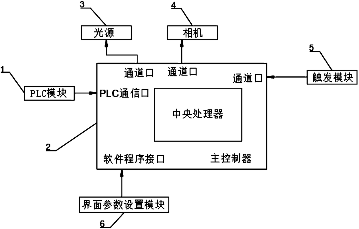
[0034] like Figure 1-2 As shown, a high-speed control light source camera trigger control system includes a PLC module 1, a main controller 2, a light source 3, a camera 4, a trigger module 5 and an interface parameter setting module 6, and the output terminal of the PLC module 1 is connected to the The first input end of the main controller 2 is connected, the first output end of the main controller 2 is connected to the input end of the light source 3, the second output end of the main controller 2 is connected to the input of the camera 4 The second input end of the main controller 2 is connected to the output end of the trigger module 5 , and the output end of the interface parameter setting module 6 is connected to the third input end of the main controller 2 .
Embodiment 2
[0036] like Figure 1-2 As shown, this embodiment is improved on the basis of Embodiment 1, and the control system of the PLC module 1 gives a synchronization start signal and a synchronization end signal.
[0037] Described master controller 2 comprises the circuit board of electronic welding, and described circuit board is provided with central processing unit, several channel ports, PLC communication port and software program interface, and described channel port is used for connecting trigger module 5, light source 3 and camera4.
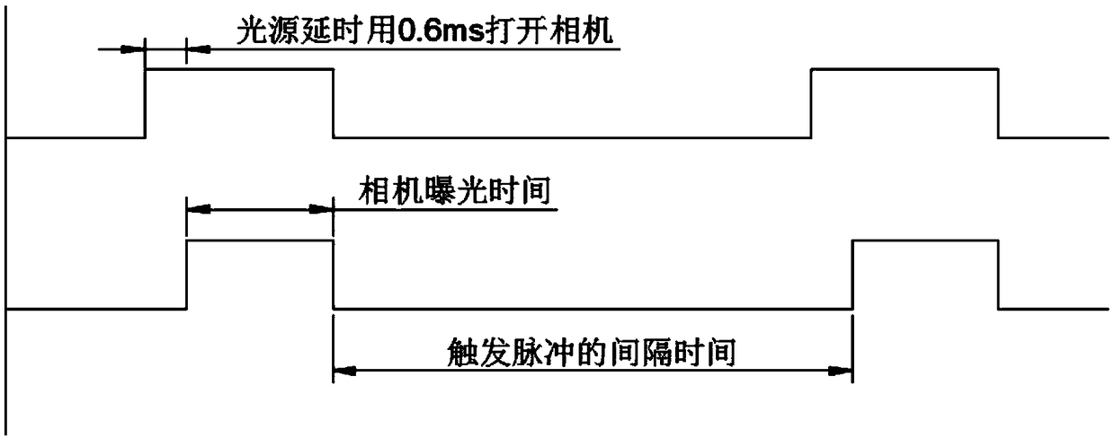
[0038] The main controller 2 implements the triggering mode through the triggering module 5. Within the synchronization cycle time, the trigger pulse is evenly divided according to the number of pictures taken, and the camera 4 or the light source 3 is triggered sequentially according to the priority within the pulse time.
[0039] The interface parameter setting module 6 is to set the trigger mode, setting parameters and statistics for the mai...
Embodiment 3
[0041] like Figure 1-2 As shown, a high-speed control method for controlling the light source camera 4 to trigger the control system includes the following steps:
[0042] S1, setting parameters in the interface parameter setting module 6;
[0043] S2. Write the parameters in S1 into the main controller 2;
[0044] S3. When the device is running, the synchronous start signal of the PLC module 1 and the trigger module 5 (channel) simultaneously control the triggering of the light source 3 and the camera 4 .
PUM
Abstract
The invention discloses a control system for high-speed control light source camera triggering and a control method. The control system comprises a PLC module, a main controller, a light source, a camera, a triggering module and an interface parameter setting module; an output end of the PLC module is connected with a first input end of the main controller; a first output end of the main controller is connected with an input end of the light source; a second output end of the main controller is connected with an input end of the camera; a second input end of the main controller is connected with an output end of the triggering module; and an output end of the interface parameter setting module is connected with a third input end of the main controller. According to the invention, the number of priority groups can be improved, and light source interference of an image is eliminated.
Description
technical field [0001] The present invention relates to the technical field of light source camera triggering, in particular to a high-speed control system and method for controlling light source camera triggering. Background technique [0002] Traditional control camera triggering, software setting system parameters to control light source camera triggering, this trigger control system is suitable for equipment running at a lower speed, but it has limitations for high-speed operation of high-volume cameras, and the number of light source priorities supports less, making the camera The captured images have interference problems, and at the same time, the stability of the captured images under high output is not enough. Contents of the invention [0003] In order to solve the problems existing in the prior art, the object of the present invention is to provide a high-speed control light source camera trigger control system and control method, which has the advantages of inc...
Claims
Application Information
Patent Timeline
Application Date:The date an application was filed.
Publication Date:The date a patent or application was officially published.
First Publication Date:The earliest publication date of a patent with the same application number.
Issue Date:Publication date of the patent grant document.
PCT Entry Date:The Entry date of PCT National Phase.
Estimated Expiry Date:The statutory expiry date of a patent right according to the Patent Law, and it is the longest term of protection that the patent right can achieve without the termination of the patent right due to other reasons(Term extension factor has been taken into account ).
Invalid Date:Actual expiry date is based on effective date or publication date of legal transaction data of invalid patent.

