Medical imaging system, scanning table control method and device and storage medium

A medical imaging and scanning bed technology, which is applied in the fields of devices and storage media, medical imaging systems, and scanning bed control methods, can solve the problems of increasing image scanning preparation time, affecting imaging quality, and cumbersome operation process, so as to reduce the preparation time in the early stage , Improving the imaging quality and improving the effect of positioning accuracy

Pending Publication Date: 2019-02-22
SHANGHAI UNITED IMAGING HEALTHCARE
View PDF6 Cites 12 Cited by
  • Summary
  • Abstract
  • Description
  • Claims
  • Application Information

AI Technical Summary

Problems solved by technology

[0004] Due to the need for manual pre-scanning preparations in the prior art, the operation process is cumbersome, which increases the preparation time for image scanning and reduces the imaging efficiency
At the same time, due to the individual differences of operators, there are deviations in the positioning of the scanning position and the movement of the scanning table, which affects the imaging quality

Method used


Image

  • Medical imaging system, scanning table control method and device and storage medium
  • Medical imaging system, scanning table control method and device and storage medium
  • Medical imaging system, scanning table control method and device and storage medium

Examples


Embodiment 1

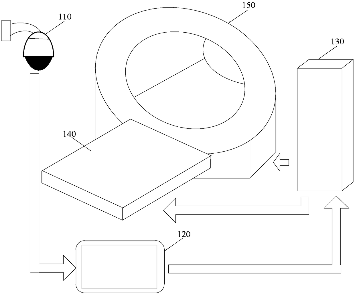
[0027] figure 1 It is a schematic structural diagram of a medical imaging system in Embodiment 1 of the present invention. Such as figure 1 The medical imaging system shown includes: a camera 110, a control terminal 120, a control machine 130, a scanning bed 140 and a scanning device 150;

[0028] Wherein, the camera 110 is used to collect reference images of the scanning bed 140;

[0029] The control terminal 120 is connected to the camera 110, and is used to acquire the reference image, and after receiving the positioning line position instruction, determine the target position of the positioning line in the reference image;

[0030] The control terminal 120 is communicatively connected with the control machine 130, and is also used to determine the target bed code of the scanning bed 140 according to the target position of the positioning line, and generate a bed moving instruction based on the target bed code and send it to the Said control machine 130;

[0031] The co...

Embodiment 2

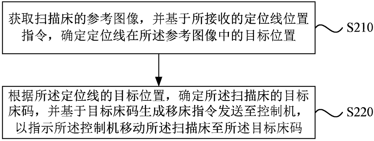
[0052] figure 2 It is a flowchart of a scanning bed control method in Embodiment 2 of the present invention. The embodiment of the present invention is applicable to the situation where the medical imaging system involved in the technical solutions of the above-mentioned embodiments is used for image scanning. In the control terminal of the video system.

[0053] Such as figure 2 A method for controlling a scanning table includes:

[0054] S210. Acquire a reference image of the scanning bed, and determine a target position of the positioning line in the reference image based on the received positioning line position instruction.

[0055] Wherein, after the control terminal obtains the reference image of the scanning bed, the reference image will be displayed on the terminal interface. When displaying the reference image, a positioning line is displayed at the same time, which is used to identify the to-be-scanned area of ​​the to-be-scanned object to a certain extent.

...

Embodiment 3

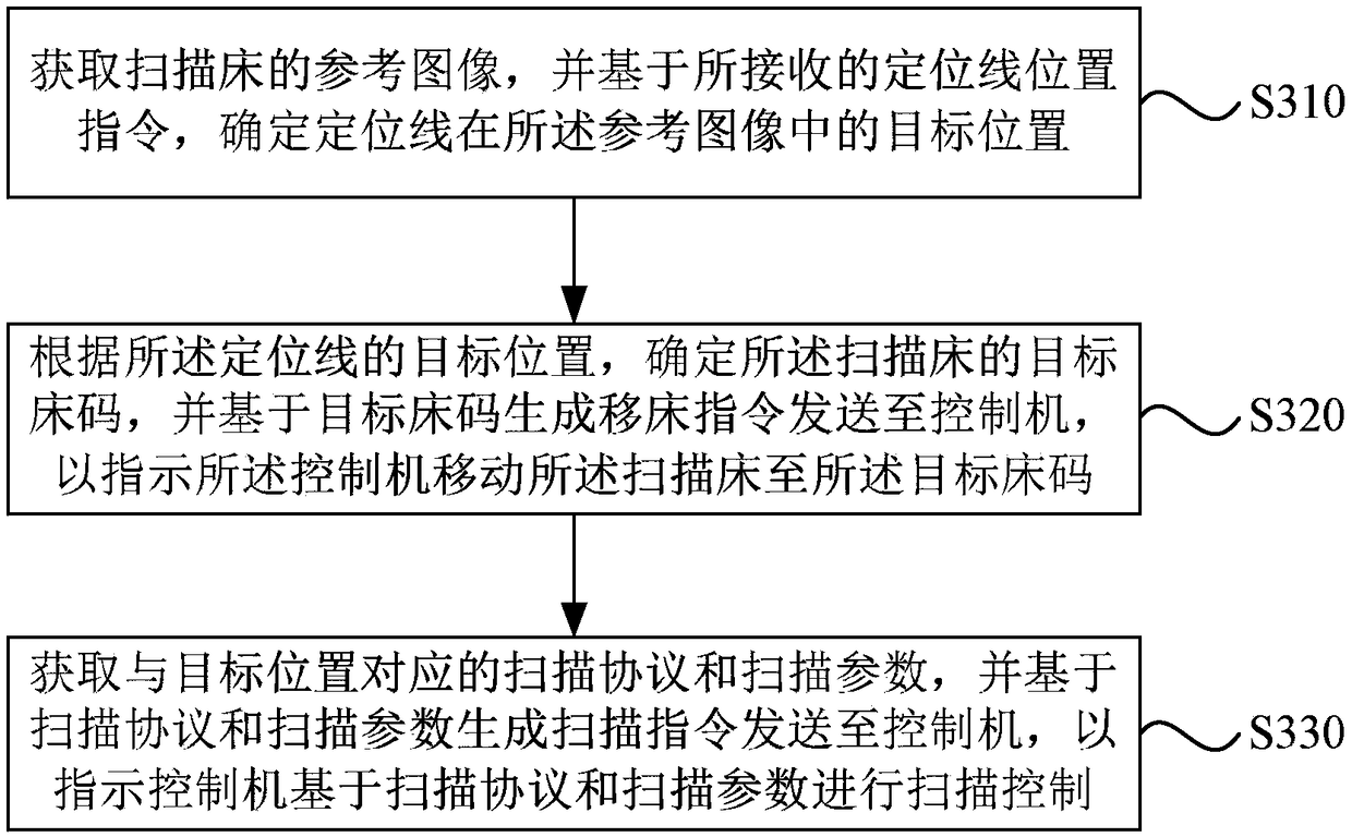
[0070] image 3 It is a flowchart of a scanning bed control method in Embodiment 3 of the present invention. The embodiments of the present invention perform additional optimization on the basis of the technical solutions of the foregoing embodiments.

[0071] Further, after the operation "send the bed moving instruction to the control machine", add "obtain the scanning protocol and scanning parameters corresponding to the target position, and generate a scanning instruction based on the scanning protocol and the scanning parameters to send to the control machine, so as to instruct the control machine to perform scan control based on the scanning protocol and the scanning parameters”, so as to realize the integrated control of the positioning of the scanning bed, the movement of the scanning bed and the image scanning process.

[0072] Such as image 3 A method for controlling a scanning table includes:

[0073] S310. Acquire a reference image of the scanning bed, and deter...


PUM


Abstract

The embodiment of the invention discloses a medical imaging system, a scanning table control method and device and a storage medium. The medical imaging system includes a scanning table and a controlmachine and further includes a camera and a control terminal; the camera is used for collecting reference images of the scanning table; the control terminal is connected with the camera and is used for acquiring the reference images and determining the target positions of positioning lines in the reference images after positioning line position commands are received; the control terminal is in communication connection with the control machine and is further used for determining a target table number of the scanning table according to the target positions of the positioning lines, generating atable movement command on the basis of the target table number and sending the table movement command to the control machine; the control machine is in communication connection with scanning table andis used for receiving the table movement command and controlling the scanning table to move to the position corresponding to the target table number. By adopting the technical scheme, early-stage preparation time for image scanning is shortened, thus, the imaging efficiency is improved, the positioning accuracy of scanning positions is also improved, and therefore the imaging quality is improved.

Description

technical field [0001] Embodiments of the present invention relate to the field of medical equipment, and in particular, to a medical imaging system, a scanning bed control method, device, and storage medium. Background technique [0002] Medical imaging refers to the human body or a certain part of the human body, which interacts with the human body in a non-invasive manner with the help of a certain medium, and then obtains images of the internal tissues and organs of the human body to assist doctors in the diagnosis and treatment of diseases. [0003] In the prior art, before scanning medical images, it is usually necessary to locate the scanning position by laser light, and manually control the scanning table to move to the corresponding position. [0004] In the prior art, pre-scanning preparatory work needs to be manually performed, and the operation process is cumbersome, thus increasing the preparation time for image scanning and reducing imaging efficiency. At the ...

Claims


Application Information

Patent Timeline
Patent Type & Authority Applications(China)
IPC IPC(8): A61G13/00A61G13/02
CPCA61G13/0018A61G13/02A61G2205/00A61G2203/20A61G2203/22
Inventor 陈文松姚峰
Owner SHANGHAI UNITED IMAGING HEALTHCARE
Why Eureka
Try Eureka