Petroleum pipeline dredger

A technology for oil pipelines and dredgers, which is applied in the direction of chemical instruments and methods, cleaning hollow objects, cleaning methods and appliances, etc. It can solve the problems of long time consumption, high labor intensity of dredging oil pipelines, and non-universal dredging equipment, etc., to achieve intelligent cleaning , easy to carry, simple structure

Pending Publication Date: 2019-02-22
四川富利斯达石油科技发展有限公司
View PDF5 Cites 1 Cited by
  • Summary
  • Abstract
  • Description
  • Claims
  • Application Information

AI Technical Summary

Problems solved by technology

[0003] Aiming at the currently used oil pipeline dredging labor intensity is high, time-consuming, dredging equipment cannot be used universally, and oil pipeline bends cannot be dredged with conventional tools, the present invention provides an oil pipeline dredger that can effectively solve the above problems

Method used


Image

  • Petroleum pipeline dredger
  • Petroleum pipeline dredger
  • Petroleum pipeline dredger

Examples


Embodiment 1

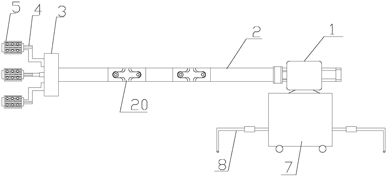
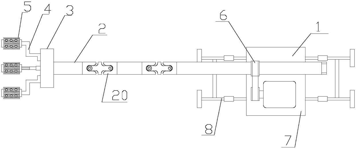
[0025] Such as Figure 1~2 Shown as a preferred embodiment, the motor 1 of the oil pipeline dredger is installed on the base 7, the motor 1 is connected to the rotating shaft 2, the rotation of the motor 1 drives the rotating shaft 2 to rotate, the rotating shaft 2 is fixedly connected to an adjustable chuck 3, and the rotating shaft 2 The axis coincides with the axis of the adjustable chuck 3, and a plurality of connecting claws 4 are arranged on the end face of the adjustable chuck 3. The adjustable chuck 3 and connecting claws 4 are similar to the three-jaw adjustable chuck used on the machine tool The radial position of the connecting claws 4 on the end face of the adjustable chuck 3 can be adjusted by the adjusting device, so as to realize the "opening" and "shrinking" of the multiple connecting claws 4 in the radial direction. For example, by setting the connecting claw 4 and the adjustable chuck 3 through the threaded connection of the end face, and setting the limit de...

Embodiment 2

[0029] Such as Figure 4 As shown, the adjustable chuck 3 of this embodiment uses the second motor 34 to adjust the position of the connecting claw 4 in the radial direction of the adjustable chuck. Specifically, the adjustable chuck 3 includes a fixed disk 31, a rotating disk 32, and a blocking disk 33; the fixed disk 31, the rotating disk 32, and the blocking disk 33 are coaxially arranged; one end of the fixed disk 31 is connected to the rotating shaft 2. The other end of the fixed disc 31 is provided with a cavity 311 for accommodating the turntable 32, the turntable 32 is placed in the cavity 311, and the turntable 32 and the fixed disc 31 are rotatably connected, and the rotatably connected This is achieved by inserting the matching shaft 310 on the fixed disk 31 into the matching hole 321 of the rotating disk 32 . The turntable 32 has an end face thread 320; the connecting claw 4 consists of three parts, the first part 40 has an end face matching thread 400 matched wit...

Embodiment 3

[0031] The friction head 5 can be detachably connected with the connecting claw 4, so that when the friction head 5 is damaged, it can be replaced.


PUM


Abstract

The invention discloses a petroleum pipeline dredger. The petroleum pipeline dredger comprises a motor, a rotating shaft and friction heads, wherein the rotating shaft is connected to the motor; the petroleum pipeline dredger further comprises an adjustable chuck, the adjustable chuck is fixedly connected to the rotating shaft, and the axis of the adjustable chuck coincides with the axis of the rotating shaft; the petroleum pipeline dredger further comprises a plurality of connecting claws, the connecting claws are uniformly distributed on the end surface of the adjustable chuck in the circumferential direction, and the position of the connecting claws in the radial direction of the end surface of the adjustable chuck is adjustable; the number of the friction heads is corresponding to thenumber of the connecting claws, the friction heads and the connecting claws are connected in a one-to-one mode; a plurality of universal joints are connected in the middle of the rotating shaft; and the petroleum pipeline dredger further comprises a base, and the motor is fixed on the base.

Description

Technical field: [0001] The invention relates to dredging oil pipelines, in particular to an oil pipeline dredging device. Background technique: [0002] Petroleum pipelines are needed to transport oil and gas in petroleum development. Since petroleum contains a lot of impurities, over time, many impurities will adhere to the pipeline wall, affecting the flow of pipelines, and even causing siltation and blockage. Moreover, these impurities also contain corrosive substances, which will corrode the pipeline over time and cause leakage. The existing dredging equipment is labor-intensive and time-consuming, and due to the different pipe specifications, the dredging equipment cannot be used universally. Because some oil pipelines also have a curved shape, the curved position cannot be dredged with conventional tools. Invention content: [0003] Aiming at the currently used oil pipeline dredging is labor-intensive and time-consuming, dredging equipment cannot be used universal...

Claims


Application Information

Patent Timeline
Patent Type & Authority Applications(China)
IPC IPC(8): B08B9/051B08B13/00
CPCB08B9/051B08B13/00
Inventor 彭远进
Owner 四川富利斯达石油科技发展有限公司
Why Eureka
Try Eureka