Device for skew rolling the tubular or rod shaped rolling piece

A rolled piece and rod-shaped technology, applied in the field of skew rolling equipment, can solve the problems of increasing the rolling speed, increasing the wear, and uneven operation of the rolling piece, avoiding the rotation of the rolling piece, reducing the centrifugal force, and improving the productivity. Effect

Active Publication Date: 2009-03-11
KOCKS TECH GMBH & CO
View PDF3 Cites 2 Cited by
  • Summary
  • Abstract
  • Description
  • Claims
  • Application Information

AI Technical Summary

Problems solved by technology

Second, the rolling stock and possible internal molds require complex guides
Third, the flow rate of the rolling stock and thus the production capacity of the equipment is strictly limited
However, this also increases the rotational speed of the rolled piece, which leads to an unstable operation of the rolled piece, with the consequences of damage to the rolled piece, technical failure of the machine and increased wear
In addition, during rolling due to the higher roll speeds the workpiece must be accelerated more strongly, which leads to roll slippage and thus scratching problems
Fourth, the rolling stock rotating about its longitudinal axis prevents continuous finishing rolling in the downstream longitudinal rolling mill stands at short intervals.
The disadvantage of this structure is that it is necessary to have bevel gears with axes staggered
This can only be calculated and machined by a small number of highly specialized manufacturing plants, requiring special tools and correspondingly expensive production costs

Method used


Image

  • Device for skew rolling the tubular or rod shaped rolling piece
  • Device for skew rolling the tubular or rod shaped rolling piece
  • Device for skew rolling the tubular or rod shaped rolling piece

Examples


Embodiment Construction

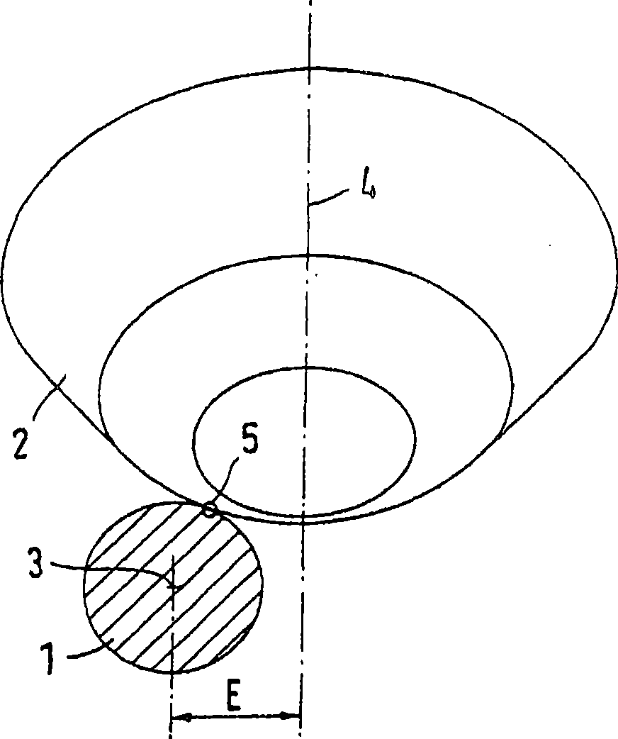
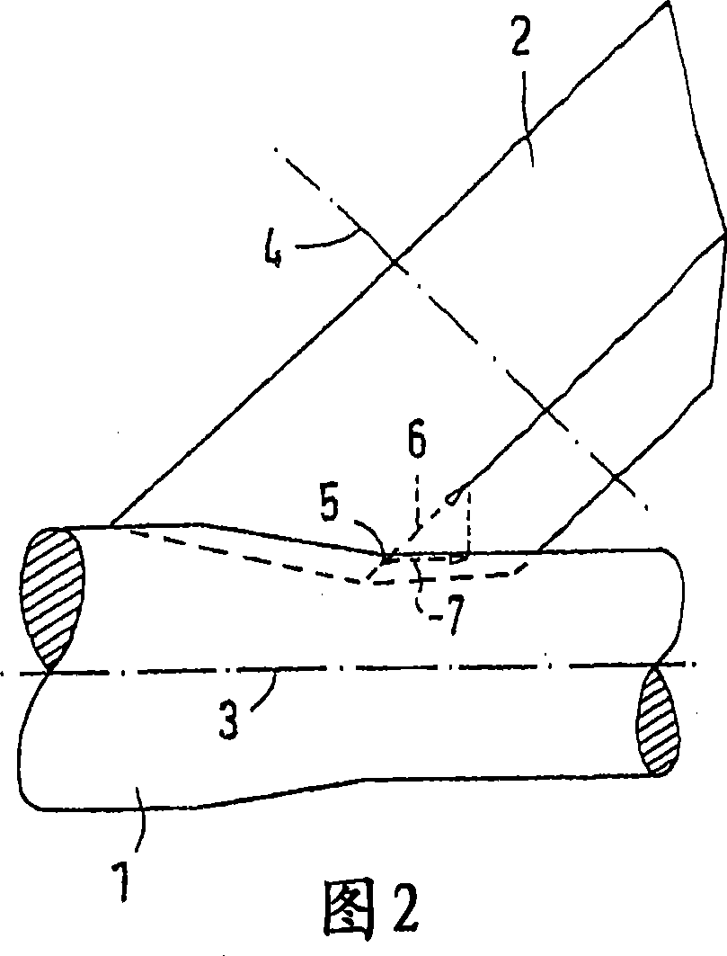
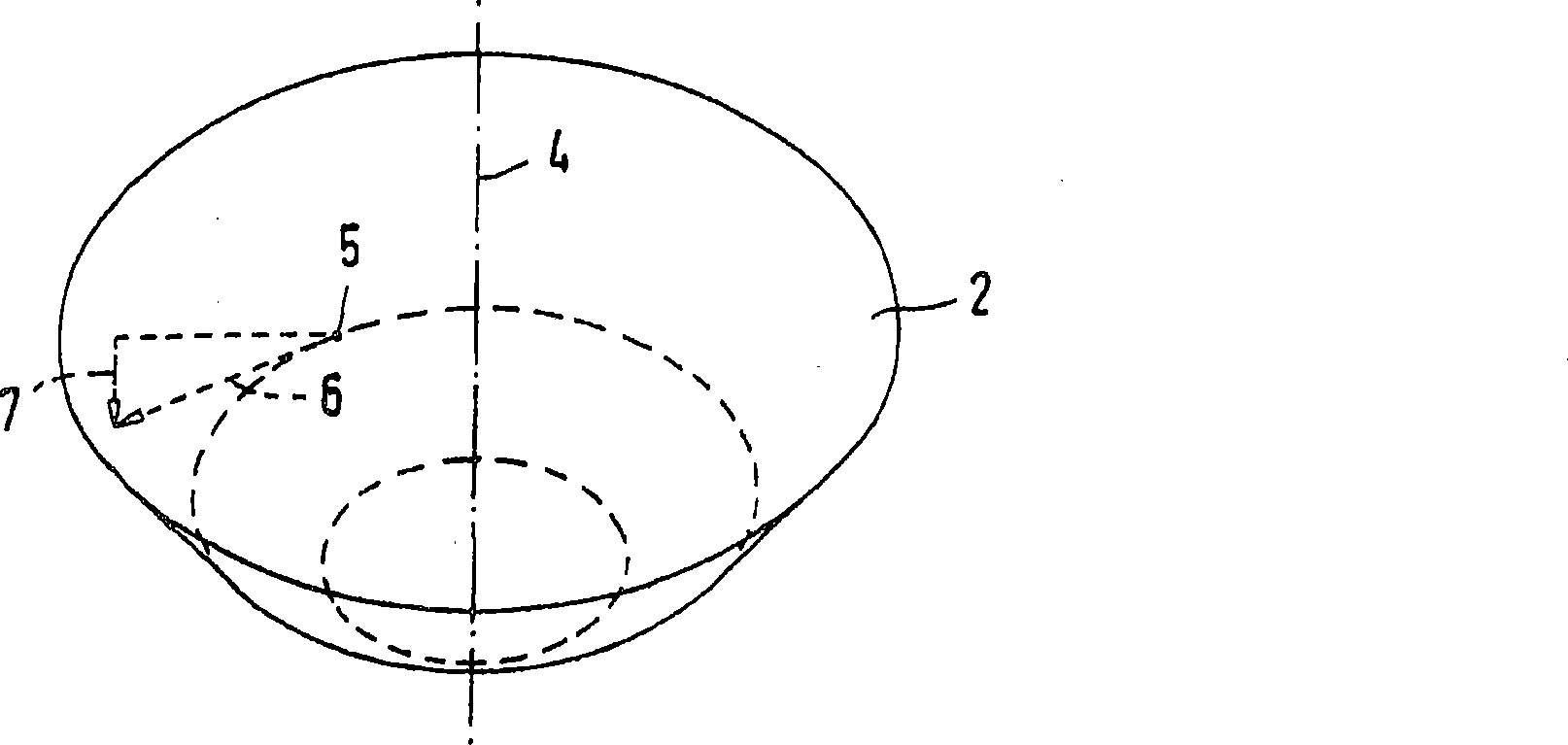
[0022] figure 1 The cross-section of the rolling stock 1 is shown in front view. The rolling stock 1 shown in the figure is a solid rod. However, the rolling stock 1 can also consist of a tube or tube blank, in which an inner mold, for example a mandrel, can be located. The rolled piece 1 is processed and formed by a plurality of rolls 2 surrounding the rolled piece 1. Figures 1 to 3 Only one roll 2 is shown in each case. Each roll 2 orbits around the longitudinal axis 3 of the rolled piece in a planetary manner, and the longitudinal axis 3 of the rolled piece is perpendicular to figure 1 paper extension. Here, the roll 2 rotates about its roll axis 4 and rolls on the outer surface of the rolling stock 1 . In the example shown, the roll 2 is substantially conical, but has the shape of two truncated cones with abutting outer surfaces of different slopes. The shape described can be seen particularly clearly in the side view in FIG. 2 , which also shows that the roll axis ...


PUM


Abstract

The invention relates to a device for obliquely rolling a tubular or rod-shaped rolled piece, which comprises two or a plurality of driven rollers rotating around the longitudinal axis of the rolled piece. The axis of the roller obliquely extends in mode of an oblique angle relatively to the longitudinal axis of the rolled piece; in order to feed the rolled piece, the axis of the roller obliquelyextends in such a plane that the plane extends beside the longitudinal axis of the rolled piece by a radial distance in parallel when the plane is observed along the longitudinal axis of the rolled piece positively or negatively, a driving gear around the axis of each roller is meshed with a sun gear around the longitudinal axis of the rolled piece through a bevel gear tooth, the central line of the driving gear also extends in one plane of the longitudinal axis of the rolled piece, the driving gear meshed with the sun gear is provided with inner teeth in a hub area, outer teeth supporting each roller are meshed with the inner teeth, axes are staggered and supported relatively to the central line of the driving gear so that the axes obliquely extend in such a plane that the plane extends beside the longitudinal axis of the rolled piece by a radial distance in parallel when the plane is observed along the longitudinal axis of the rolled piece positively or negatively.

Description

technical field [0001] The invention relates to a plant for cross-rolling tubular or rod-shaped rolling stock. Background technique [0002] Cross-rolling equipment is mainly used in the production of seamless tubes, for example, to perforate a circular billet and thereby produce a hollow tube blank with a thicker wall, or to stretch such a hollow tube blank to reduce its wall thickness, or Used for tube expansion. It is also known that such devices are also used for stretching and reducing the cross-section of rod-shaped, ie solid rolling stock. [0003] In conventional plants of this type, the rolling stock is formed while turning between rolls rotating in the same direction of rotation. In order to achieve continuous feeding of the rolled piece in the longitudinal direction, the axis of the roll is arranged at an offset angle relative to the longitudinal axis of the rolled piece, so a component along the longitudinal direction of the rolled piece is generated by the per...

Claims


Application Information

Patent Timeline
Patent Type & Authority Applications(China)
IPC IPC(8): B21B13/00B21B19/02
CPCB21B13/008B21B19/02
Inventor H·波特霍夫
Owner KOCKS TECH GMBH & CO
Why Eureka
Try Eureka