

Damping joint for main manipulator
A main operator and damping technology, applied in the field of robotic arms, can solve problems such as the inability of its own properties to be uniform and constant, the inability to accurately adjust the size of the friction force, the difficulty and uncertainty of implementation, etc., so as to improve the safety of use and enhance the operation. Feel the effect of eliminating the error of the action
- Summary
- Abstract
- Description
- Claims
- Application Information
AI Technical Summary
Problems solved by technology
Method used
Image

Examples
Embodiment 1
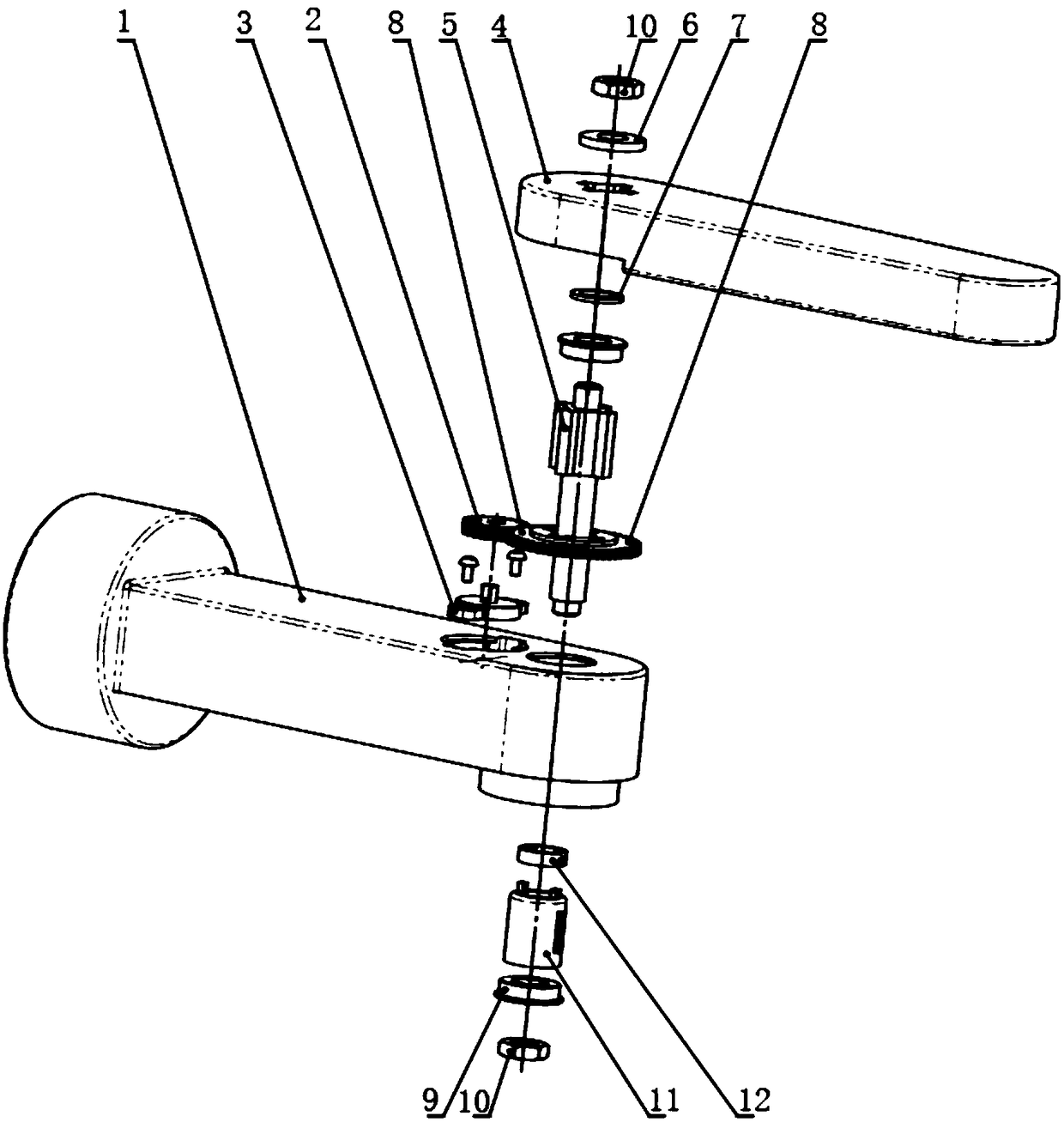
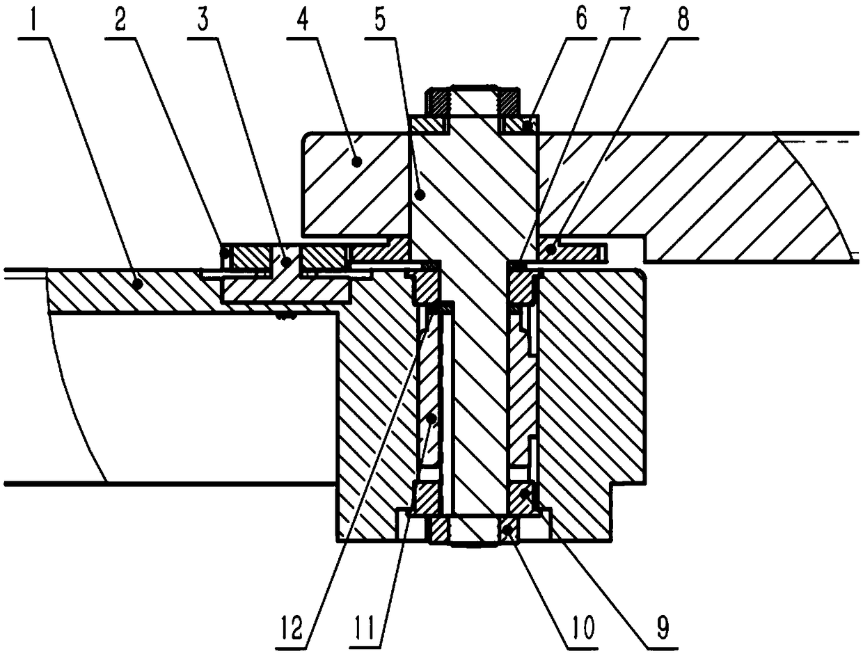
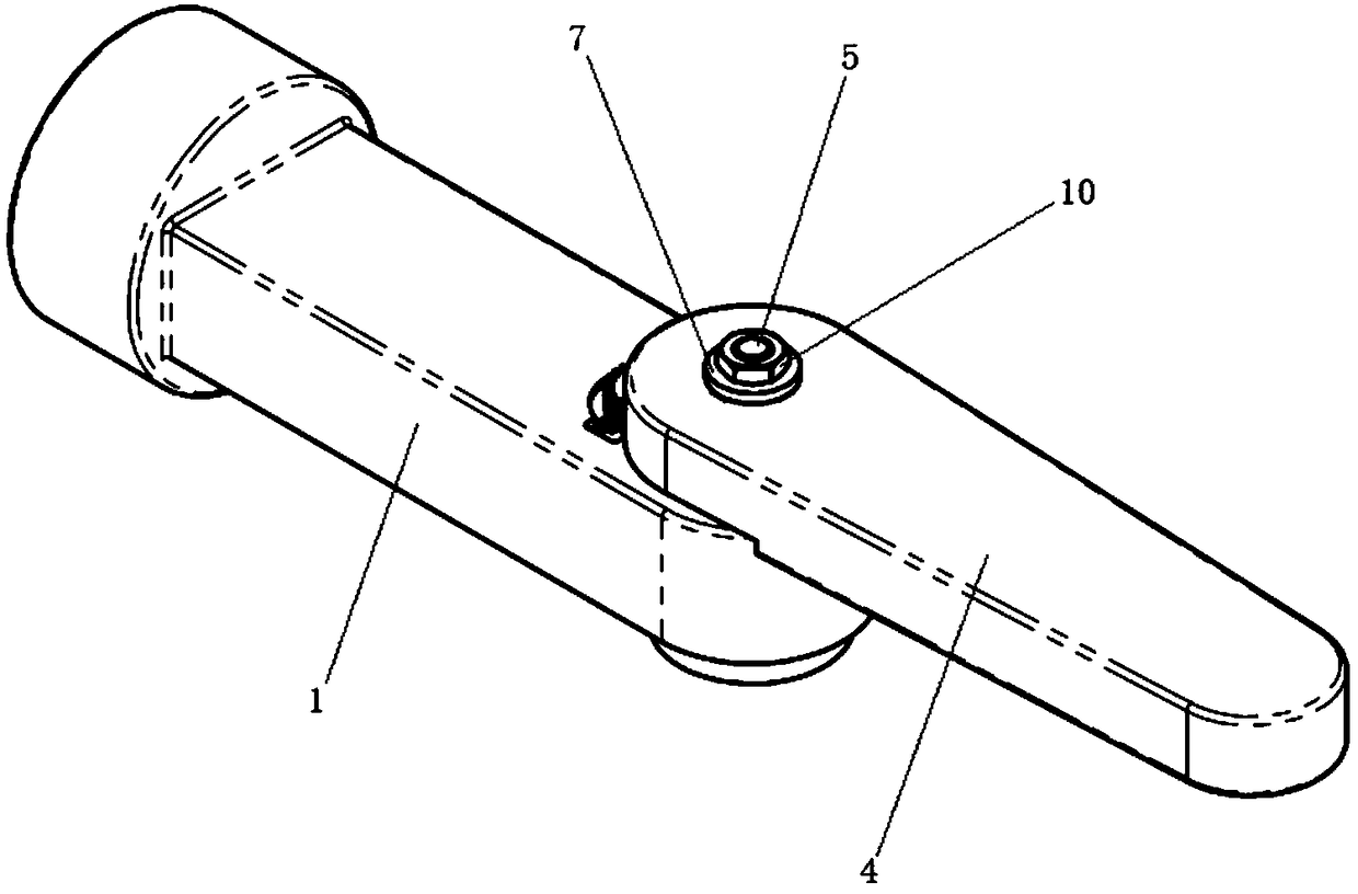
[0038] combine Figure 1-3 , Figure 5-6 As shown, this embodiment provides a damping joint for the main operator, including: a first connecting rod 1; a second connecting rod 4, the second connecting rod 4 is rotationally connected with the first connecting rod 1; a rotating shaft assembly, The rotating shaft assembly includes a key shaft 5 and a bearing 9. The key shaft 5 passes through the first connecting rod 1 and the second connecting rod 4 and is locked and fixed in the axial direction, and the key shaft 5 includes a fixed spline segment 51 and a cylindrical segment 52 The spline section 51 is keyed to the second connecting rod 4, and the cylindrical section 52 is connected to the first connecting rod 1 through the bearing 9; the damping assembly, the damping assembly includes the first rotation damper 11, and the first rotation damper 11 is sleeved on the key shaft 5, the first rotation damper 11 includes a casing 112 and a swivel 111, the casing 112 and the swivel 11...
Embodiment 2
[0049] combine Figure 1-2 , Figure 4 As mentioned above, the difference between this embodiment and the above embodiment is that the damping assembly also includes a first gear 2, a second gear 8 and a second rotation damper 3, the first gear 2 and the second gear 8 mesh with each other, and the second rotation damper 3 includes a relatively rotatable housing 32 and a shaft 31, the housing 32 is fixed to the first connecting rod 1, the first gear 2 and the second gear 8 are keyed to the shaft 31 and the spline segment 51 respectively; the second gear 8 is connected to the key shaft 5 are linked to rotate and transmit the rotation to the first gear 2, the first gear 2 drives the rotating shaft 31 to rotate, and the rotating shaft 31 and the housing 32 rotate relative to generate braking torque.
[0050] The working principle of the second rotary damper 3 is the same as that of the first rotary damper 11. It also has a casing 32 filled with damping grease and a rotating shaft...
Embodiment 3
[0056] The difference between this embodiment and the above embodiments is that there are multiple first rotation dampers 11 and special-shaped shaft clamps 12, and multiple special-shaped shaft clamps 12 and first rotation dampers 11 are sequentially arranged in the bearing chamber of the first connecting rod 1 , used to adjust the torque value of the damping joint.
[0057] as in figure 2 One or more sets of special-shaped shaft clamps 12 and the first rotation damper 11 are connected under the first rotation damper 11 in the middle, so as to realize the series connection of multiple first rotation dampers 11, and further adjust the damping size of the main operator's joint.
[0058] Preferably, there are multiple second rotary dampers 3, and multiple second rotary dampers 3 are distributed on the first connecting rod 1 at intervals, and connected in series through multiple first gears 2 to adjust the torque of the damping joints value. as in figure 2 One or more sets o...
PUM
 Abstract
Description
Claims
Application Information