Die cutting device for soft metal film

A soft film, die-cutting technology, applied in metal processing and other directions, can solve the problems of shortening the service life of the mold, low production efficiency, waste of resources, etc., to achieve the effect of convenient storage, reduced manual use, and not easy to be polluted

Inactive Publication Date: 2019-02-22
昆山摩建电子科技有限公司
View PDF6 Cites 0 Cited by
  • Summary
  • Abstract
  • Description
  • Claims
  • Application Information

AI Technical Summary

Problems solved by technology

However, because there is no buffer, the existing punch directly presses down without buffering and contacts the lower template during die-cutting, which will cause needle damage, shorten the service life of the mold, waste resources, and the production efficiency is not high

Method used


Image

  • Die cutting device for soft metal film
  • Die cutting device for soft metal film

Examples


Embodiment 1

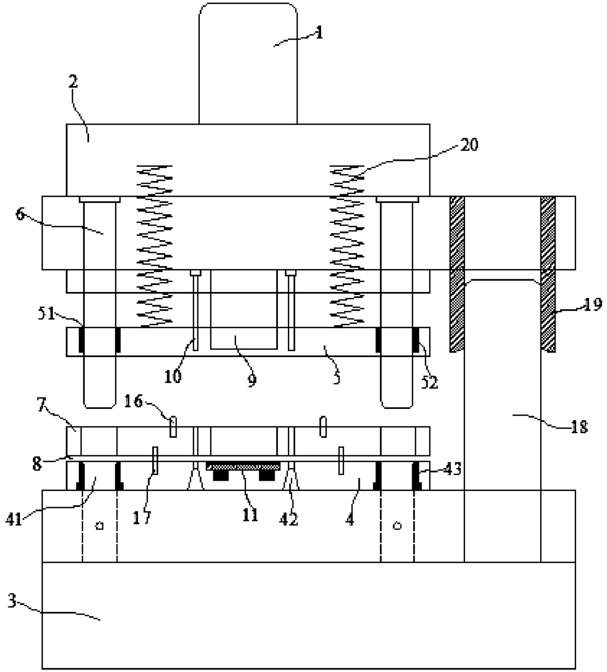
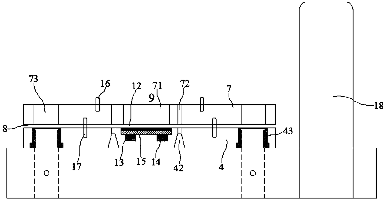
[0024] Embodiment 1: A kind of die-cutting device that is used for metal soft film, comprises upper mold handle 1, upper formwork 2 and the lower formwork 4 that is installed on the base 3, and described upper formwork 2 is installed on the lower part of upper mold handle 1 On the surface, an upper platen 5 is located below the upper formwork 2, at least two first guide posts 6 installed on the upper formwork 2 are respectively embedded in the upper through holes 51 of the upper platen 5, and an intermediate plate 7 is located above the lower formwork 4. Between the plate 7 and the lower template 4, there is a gap 8 for micro-mucosa embedding, a punch 9 and a punch needle 10 are respectively installed on the upper template 2, and a punch for the punch 9 to be embedded is arranged on the middle plate 7. Head through hole 71, pin hole 72 for inserting punching needle 10 and middle through hole 73 for inserting first guide post 6;

[0025] The middle plate 7 is located on both si...

Embodiment 2

[0031] Embodiment 2: A kind of die-cutting device that is used for metal soft film, comprises upper mold handle 1, upper formwork 2 and the lower formwork 4 that is installed on the base 3, and described upper formwork 2 is installed on the lower part of upper mold handle 1 On the surface, an upper platen 5 is located below the upper formwork 2, at least two first guide posts 6 installed on the upper formwork 2 are respectively embedded in the upper through holes 51 of the upper platen 5, and an intermediate plate 7 is located above the lower formwork 4. Between the plate 7 and the lower template 4, there is a gap 8 for micro-mucosa embedding, a punch 9 and a punch needle 10 are respectively installed on the upper template 2, and a punch for the punch 9 to be embedded is arranged on the middle plate 7. Head through hole 71, pin hole 72 for inserting punching needle 10 and middle through hole 73 for inserting first guide post 6;

[0032] The middle plate 7 is located on both si...


PUM


Abstract

The invention discloses a die cutting device for a soft metal film. The die cutting device for the soft metal film comprises an upper die handle, an upper template and a lower template arranged on a base. The upper template is arranged on the lower surface of the upper die handle. An upper pressure plate is located below the upper template. Material belt positioning columns are correspondingly arranged in a middle plate and located on both sides of a punch through hole. The lower template is provided with a lower through hole for a first guide column to be embedded in and a blanking hole for apunching needle to be embedded in. A groove is arranged in the lower template and located under the punch through hole. The bottom of the groove is provided with at least two sub-grooves in a space mode. The sub-grooves are internally provided with magnet blocks. Magnetic stainless steel is located in the groove and is in contact with the magnet blocks located below. The surface of the magnetic stainless steel opposite to the magnet blocks is covered with a cushion pad. The die cutting device for the soft metal film reduces the force exerted by a punch on the lower template through buffering,so that a syringe needle of the punching needle is effectively protected, the service life of the punching needle is prolonged, the production efficiency is improved, a cut product is wrinkle-free, and a sawtooth-shaped incision is avoided.

Description

technical field [0001] The invention relates to the technical field of auxiliary materials for electronic components, and belongs to a die-cutting device for soft metal films. Background technique [0002] In the electronics industry, because gold foil has the advantage of obtaining higher efficiency at a lower voltage, gold foil is often used as a contact on a circuit. At this time, gold foil needs to be in a specific shape and through a certain method Fixed on the circuit board, the current production process of gold foil is to die-cut the gold foil paper and the plastic protective film laminated on the surface of the gold foil paper to obtain a fixed shape, and then remove the single die-cut product and stick it to the corresponding position. Finally, tear off the plastic protective film on the surface of the gold foil. But because there is no buffer, the existing punch directly presses down without buffering to contact with the lower template during die-cutting, which w...

Claims


Application Information

Patent Timeline
IPC IPC(8): B26F1/44B26D7/22B26D7/01B29C63/02
CPCB26D7/015B26D7/22B26F1/44B29C63/02
Inventor 欧阳卓陈文张国杆
Owner 昆山摩建电子科技有限公司
Why Eureka
Try Eureka