Vertical type winding device for composite-material thin-wall high flange cylinder and manufacturing method

A high flanged cylinder and composite material technology, applied in the field of flanged cylinder manufacturing, can solve the problems of inability to apply pressure, the texture of the flange is loose, the longitudinal fibers of the cylinder section are turned over to a predetermined position, etc., and the effect of improving work efficiency is achieved.

Pending Publication Date: 2019-02-22
HARBIN FRP INST
View PDF0 Cites 4 Cited by
  • Summary
  • Abstract
  • Description
  • Claims
  • Application Information

AI Technical Summary

Problems solved by technology

[0004] In order to solve the problem that the existing horizontal winding machine cannot turn the longitudinal fibers of the barrel section to the predetermined position and cannot apply pressure wh

Method used


Image

  • Vertical type winding device for composite-material thin-wall high flange cylinder and manufacturing method
  • Vertical type winding device for composite-material thin-wall high flange cylinder and manufacturing method

Examples


specific Embodiment approach 1

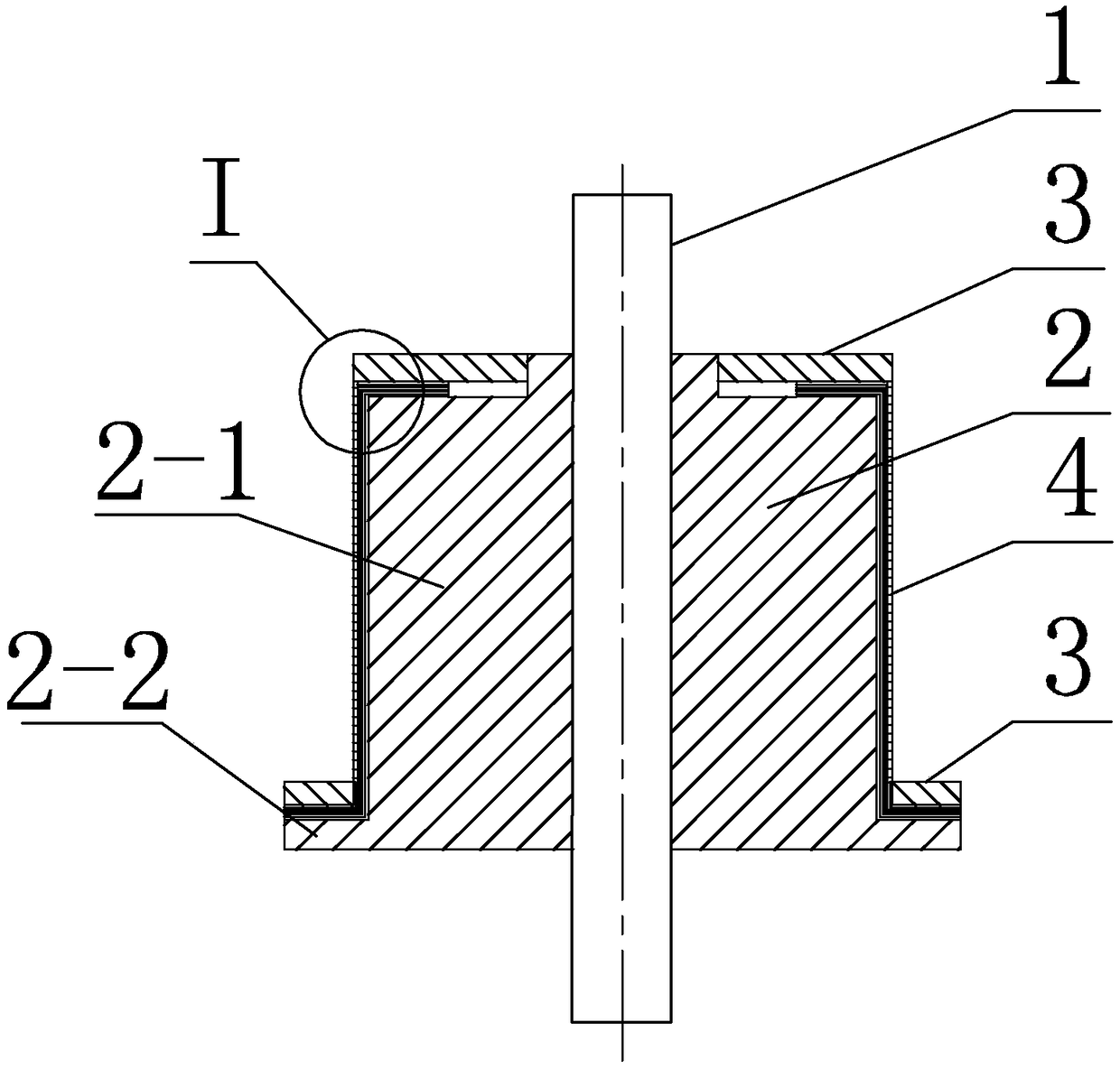
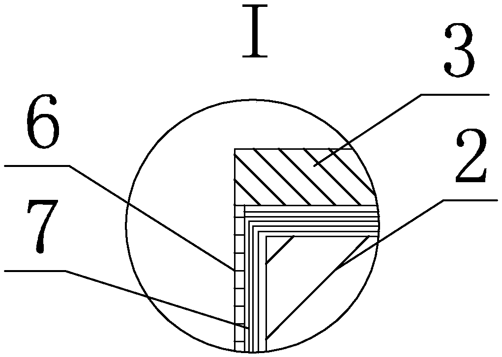
[0018] Specific implementation mode one: combine figure 1 with figure 2 To illustrate this embodiment, the vertical winding device used in this embodiment for thin-walled high-flange cylinders of composite materials includes a rotating shaft 1, a winding die 2 and two pressure plates 3;

[0019] The rotating shaft 1 is vertically arranged on the frame and can rotate. The winding die 2 is fixed on the rotating shaft 1. The winding die 2 is processed with a first cylinder 2-1 and a second cylinder 2-2. The first cylinder 2- The diameter of 1 is larger than the diameter of the second cylinder 2-2, the first cylinder 2-1 and the second cylinder 2-2 are respectively concentric with the rotating shaft 1, and the side of the first cylinder 2-1 is connected with a pressure plate by screws 3 connection, the side of the second cylinder 2-2 is connected with another pressure plate 3 by bolts.

[0020] The winding die 2 is processed with a first cylinder 2-1 and a second cylinder 2-2 t...

specific Embodiment approach 2

[0022] Specific implementation mode two: combination figure 1 To describe this embodiment, the height of the first cylinder 2-1 in this embodiment is greater than the height of the second cylinder 2-2.

[0023] Such arrangement is used to adapt to the cylinder body of the flange cylinder 4 to be wound.

[0024] Other compositions and connections are the same as in the first embodiment.

specific Embodiment approach 3

[0025] Specific implementation mode three: combination figure 1 To describe this embodiment, the two pressing plates 3 in this embodiment are both annular plates.

[0026] With such arrangement, the stress on the two flanges on the flange barrel 4 after flanging is uniform, so that the fiber arrangement of the flanging flange is uniform and accurate.

[0027] Its composition and connection relationship are the same as those in the second embodiment.


PUM


Abstract

The invention relates to a vertical type winding device for a composite-material thin-wall high flange cylinder and a manufacturing method, and relates to the technical field of flange manufacturing.The problem that the texture of a flanging flange is loosened in texture since an existing horizontal type winding machine cannot turn over a cylinder section longitudinal fiber to the preset positionwhen the flange is flanged and cannot apply pressure is solved. The vertical type winding device for the composite-material thin-wall high flange cylinder comprises a rotary shaft, a winding mold andtwo pressing plates, wherein the rotary shaft is vertically arranged on a rack and can rotate; the winding mold is fixed onto the rotary shaft; a first cylinder and a second cylinder are processed onthe winding mold; the diameter of the first cylinder is larger than the diameter of the second cylinder; the first cylinder and the second cylinder are concentric to the rotary shaft; the side surface of the first cylinder is connected with one pressing plate through a screw; and the side surface of the second cylinder is connected with the other pressing plate. The vertical type winding device for the composite-material thin-wall high flange cylinder provided by the invention is suitable for a flange cylinder with the ratio of the height to the wall thickness is more than 10 times.

Description

technical field [0001] The invention relates to the technical field of flange cylinder manufacturing, in particular to a vertical winding device and a manufacturing method for composite material thin-walled high flange cylinders. Background technique [0002] Thin-walled high-flange composite material cylinders are characterized by very thin cylinder walls, while the inner and outer flanges connected to it are very high, and the ratio of height to wall thickness is more than 10 times. The inner and outer flanging flanges of this kind of structural parts are the key parts connected with other parts, especially at the root of the flanges to bear large shear force and bending moment. In order to improve the bearing capacity of the inner and outer flanging flanges, it is necessary to A certain amount of radial fibers are laid on a specific part of the side flange, and the radial fibers must be continuous with the longitudinal fibers of the cylindrical section to make it a contin...

Claims


Application Information

Patent Timeline
IPC IPC(8): B29C70/32B29L23/00
CPCB29C70/32B29L2023/22
Inventor 侯传礼赵洪斌娄小杰杜政才
Owner HARBIN FRP INST
Why Eureka
Try Eureka