Power supply apparatus and power supplying method thereof

Active Publication Date: 2020-05-07
WIWYNN CORP
View PDF1 Cites 1 Cited by
  • Summary
  • Abstract
  • Description
  • Claims
  • Application Information

AI Technical Summary

Benefits of technology

[0006]The disclosure provides a power supply apparatus and power supplying method thereof to effectively decrease th

Problems solved by technology

It is worth noting that during the process when the switches SWA1-SWA4 are performing the switching operation, the current existing in the circuit may cause the occurrence of an electric arc situation.
In addit

Method used


Image

  • Power supply apparatus and power supplying method thereof
  • Power supply apparatus and power supplying method thereof
  • Power supply apparatus and power supplying method thereof

Examples


Embodiment Construction

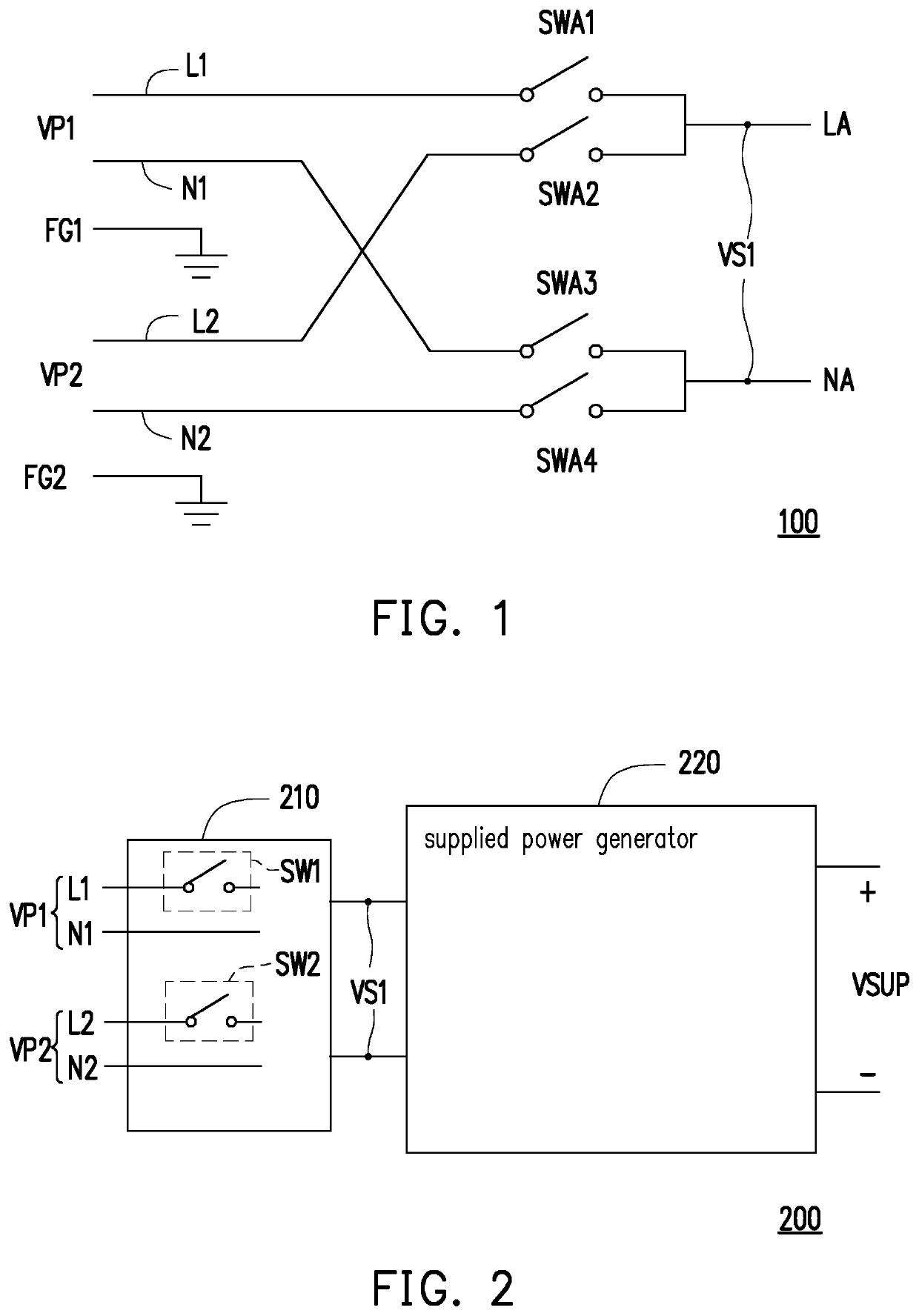
[0018]Please refer to FIG. 2. FIG. 2 shows a schematic view of a power supply apparatus of an embodiment of the disclosure. A power supply apparatus 200 includes a power switch 210 and a supplied power generator 220. The power switch 210 may be an Automatic Transfer Switch (ATS) and has switches SW1 and SW2. The switch SW1 is coupled to a fire line L1, the switch SW2 is coupled to a fire line L2. The power switch 210 receives a power VP1 through the fire line L1 and a neutral line N1, and the power switch 210 receives a power VP2 through a fire line L2 and a neutral line N2; wherein the power switch 210 receives the power VP1 through the switch SW1 to generate a selected power VS1 or receives the power VP2 through the switch SW2 to generate the selected power VS1.

[0019]The supplied power generator 220 is coupled to the power switch 210. The supplied power generator 220 receives the selected power VS1 and performs a voltage converting operation on the selected power VS1 to generate a...


PUM


Abstract

A power supply apparatus and a power supplying method thereof are provided. The power supply apparatus includes a power switch and a supplied power generator. The power switch respectively receives a first power and a second power through a first switch and a second switch. The supplied power generator converts the first power or the second power to generate a supplied power. When the supplied power generator judges the first power being cut off, during a first time period, the first switch is cut off and a voltage converting operation of the supplied power generator is stopped. During a second time period, the second switch is turned on, and the voltage converting operation of the supplied power generator is restarted after the second switch being turned on.

Description

CROSS-REFERENCE TO RELATED APPLICATION[0001]This application claims the priority benefit of Taiwan application serial no. 107139415, filed on Nov. 7, 2018. The entirety of the above-mentioned patent application is hereby incorporated by reference herein and made a part of this specification.BACKGROUNDTechnical Field[0002]The disclosure relates to a power supply apparatus and a power supplying method thereof, and particularly to a power supply apparatus of an uninterruptible power system and a power supplying method thereof.Description of Related Art[0003]In the known technical field, a power supply apparatus of an uninterruptible power system performs a switching operation between a main power and an auxiliary power through an Automatic Transfer Switch (ATS). Please refer to a circuit diagram of an ATS shown by FIG. 1. A known ATS 100 includes a plurality of switches SWA1-SWA4, wherein SWA1 and SWA2 are respectively coupled to fire lines L1 and L2, and switches SWA3 and SWA4 are res...

Claims


Application Information

Patent Timeline
IPC IPC(8): H02J9/06H02M1/42
CPCH02J9/061H02J9/068H02M1/4225H02M1/10Y02B70/10H02J9/062H02H7/10H02J9/06
Inventor HSU, KUAN-WEI
Owner WIWYNN CORP
Why Eureka
Try Eureka