Self-gravity unloading device

A self-gravity and material technology, which is applied in the field of automatic unloading devices for various shafts and rods of automobile drive shafts, and can solve problems such as unqualified shafts, falling shafts, and transfer of shafts into boxes

Pending Publication Date: 2019-02-22
耐世特凌云驱动系统(涿州)有限公司
View PDF4 Cites 7 Cited by
  • Summary
  • Abstract
  • Description
  • Claims
  • Application Information

AI Technical Summary

Problems solved by technology

There is only one single shaft unit, and the shaft inspection personnel need to carry more than 4,000 shafts from the conveyor belt to the box every day, with an average handling weight of more than 7,000 kilograms. Connect the rod, move the shaft, bend down and put it into the box. Engaging in this kind of work for a long time will cause damage to the cervical spine, lumbar spine, thoracic spine, arms and other parts of the human body. The shaft hurts oneself, so long-term engagement in this kind of work will seriously affect the physical and mental health of the shaft inspection personnel, and there will also be invalid handling such as putting the shaft into a box and transferring it, which is a waste of human labor
The production efficiency of this way of handling shafts is low, and sometimes it is too late to transport the transported shafts, which will also cause the shafts to drop, which will cause damage to the shafts, resulting in the generation of unqualified shafts

Method used


Image

  • Self-gravity unloading device
  • Self-gravity unloading device
  • Self-gravity unloading device

Examples


Embodiment Construction

[0017] The present invention will be further described below in conjunction with specific embodiments.

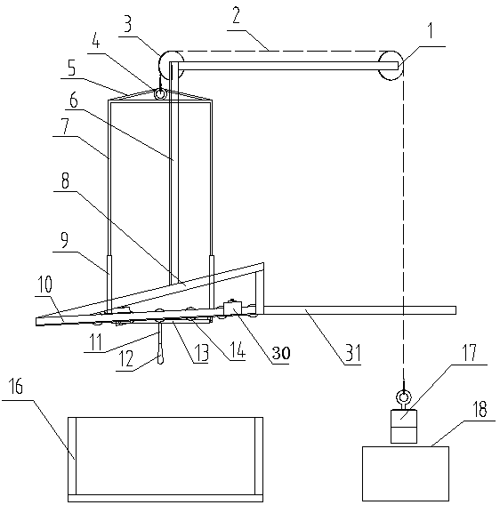
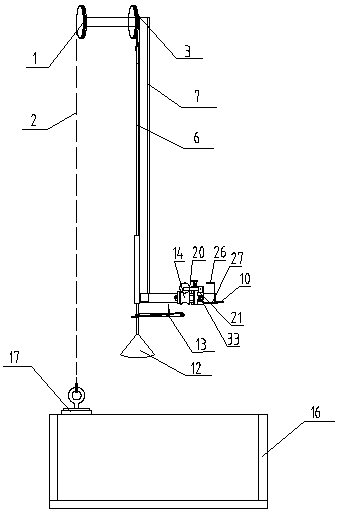
[0018] Such as figure 1 , figure 2 and image 3 As shown, the present embodiment includes a frame, a turning mechanism, a lifting mechanism and a storage and transportation box 16 .

[0019] The frame is fixed on the underframe of the workpiece processing equipment, and includes a lower end frame 10, a middle fixed frame 8 and an upper end frame 6 welded and fixed as one. The lower end frame 10 is inclined downward in a direction away from the underframe of the workpiece processing equipment; preferably, the inclination angle is any angle between 8°-15°.

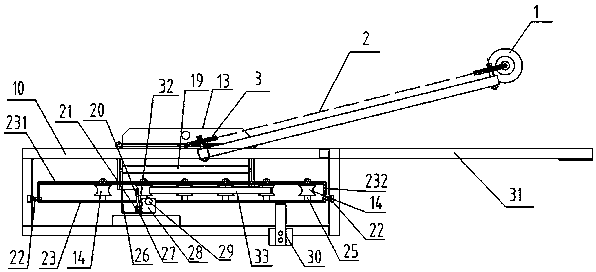
[0020] The overturn mechanism includes a deflection plate 23, a transport roller table, a counterweight plate 30 and an overturn trigger gear mechanism. The front ends of the left and right ends of the deflection disc 23 are rotatably fixed to the front ends of the left and right ends of the frame lower frame 10, and...


PUM


Abstract

The invention discloses a self-gravity unloading device. The lower end framework of a rack is mounted in an inclined mode; a turnover mechanism comprises a deflection disc which can be rotatably fixedon the lower end framework of the rack, a transportation roller way which is mounted on the rear end part of the deflection disc, a counterweight block which is fixedly arranged at the front end of the deflection disc, a movable block, a limiting plate which is fixedly arranged on the movable block, a hollow sleeve, a shifting fork shaft which is arranged in the sleeve in a penetrating mode and is fixed by a torsion spring, and a turnover trigger gear mechanism of upper and lower shifting forks which are positioned outside the sleeve and are integrated with the shifting fork shaft; when all workpieces are on the transportation roller way of the deflection disc, weight of the transportation roller way side on the deflection disc is greater than that of the counterweight board side; and a lifting mechanism comprises a lifting frame, a material tray capable of turning over, a lifting frame guide sleeve, two guide slide wheels, a steel wire rope, a counterweight and a material tray turnover mechanism, wherein a storage and transfer box is positioned below the material tray. The self-gravity unloading device can completely avoid manual unloading, greatly reduces labour intensity of a shaft lever flaw detector, improves flaw detecting efficiency of the flaw detector, and does not damage the workpieces.

Description

technical field [0001] The invention relates to an automatic unloading device for various shaft rods and bar workpieces of automobile drive shafts. Background technique [0002] The three core parts of the automobile drive shaft are the shaft, the sliding sleeve and the spherical shell. The weight of the three major parts is more than 3 kg. After the parts are manufactured, they need to be manually transported into the storage and transportation box for flaw detection. There is only one single shaft unit, and the shaft inspection personnel need to carry more than 4,000 shafts from the conveyor belt to the box every day, with an average handling weight of more than 7,000 kilograms. Connect the rod, move the shaft, bend down and put it into the box. Engaging in this kind of work for a long time will cause damage to the cervical spine, lumbar spine, thoracic spine, arms and other parts of the human body. The shaft hurts oneself, so long-term engagement in this kind of work wil...

Claims


Application Information

Patent Timeline
Patent Type & Authority Applications(China)
IPC IPC(8): B65G65/23
CPCB65G65/23B65G2207/40
Inventor 顾少伟韩波高永民郝志强王月飞
Owner 耐世特凌云驱动系统(涿州)有限公司
Why Eureka
Try Eureka