
Belt material rolling mechanism

A technology of winding mechanism and strip, which is applied in the direction of winding strips, thin material processing, transportation and packaging, etc., which can solve the problems of reduced efficiency of winding, and achieve the effect of improving the winding effect and widening the range

Pending Publication Date: 2019-02-22
四川高德特科技有限公司
View PDF8 Cites 3 Cited by
  • Summary
  • Abstract
  • Description
  • Claims
  • Application Information

AI Technical Summary

Problems solved by technology

But the existing winding device has only one winding roller. After the winding is completed, the strip on the winding roller will be taken off before the winding can be continued. Rolling takes a lot of time, which greatly reduces the efficiency of winding

Method used


Image

  • Belt material rolling mechanism
  • Belt material rolling mechanism
  • Belt material rolling mechanism

Examples


Embodiment Construction

[0024] The present invention will be described in further detail below through specific implementation examples and in conjunction with the accompanying drawings.

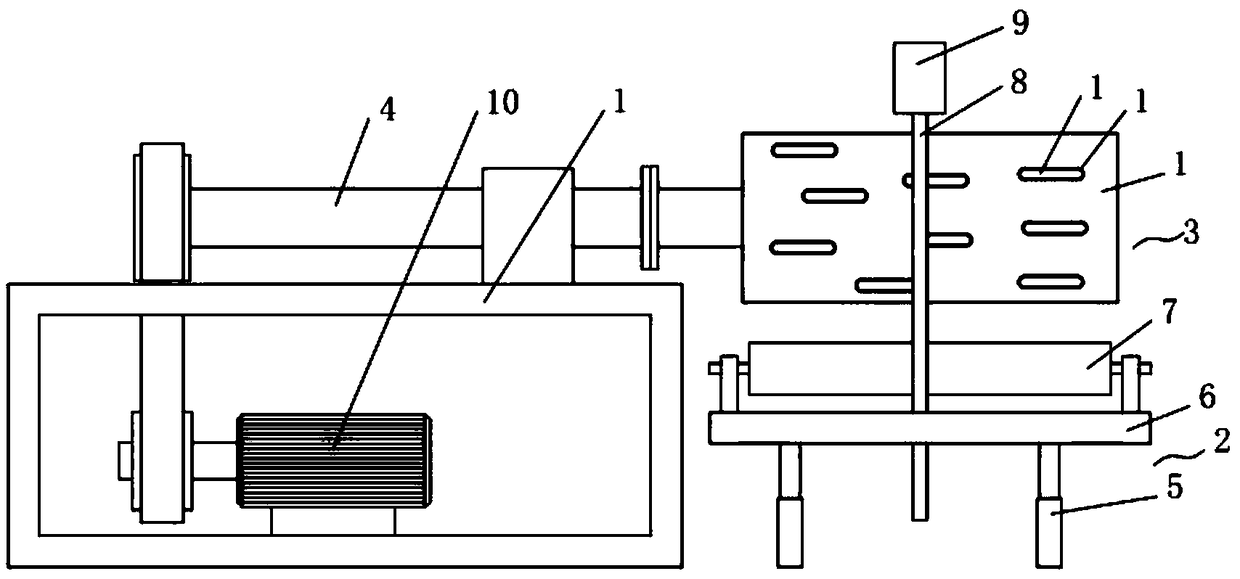
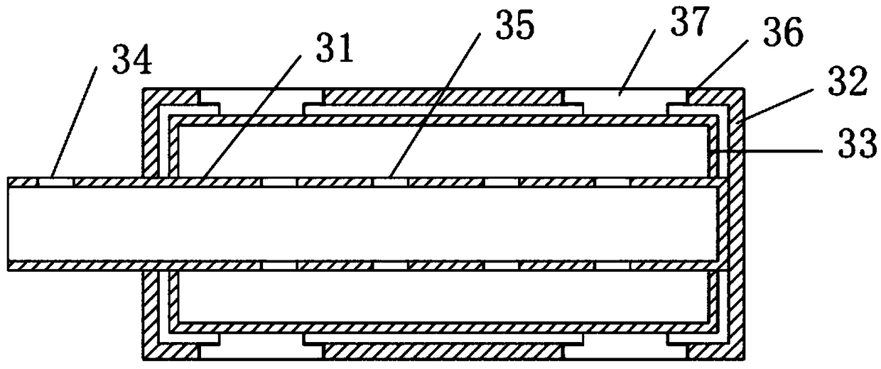
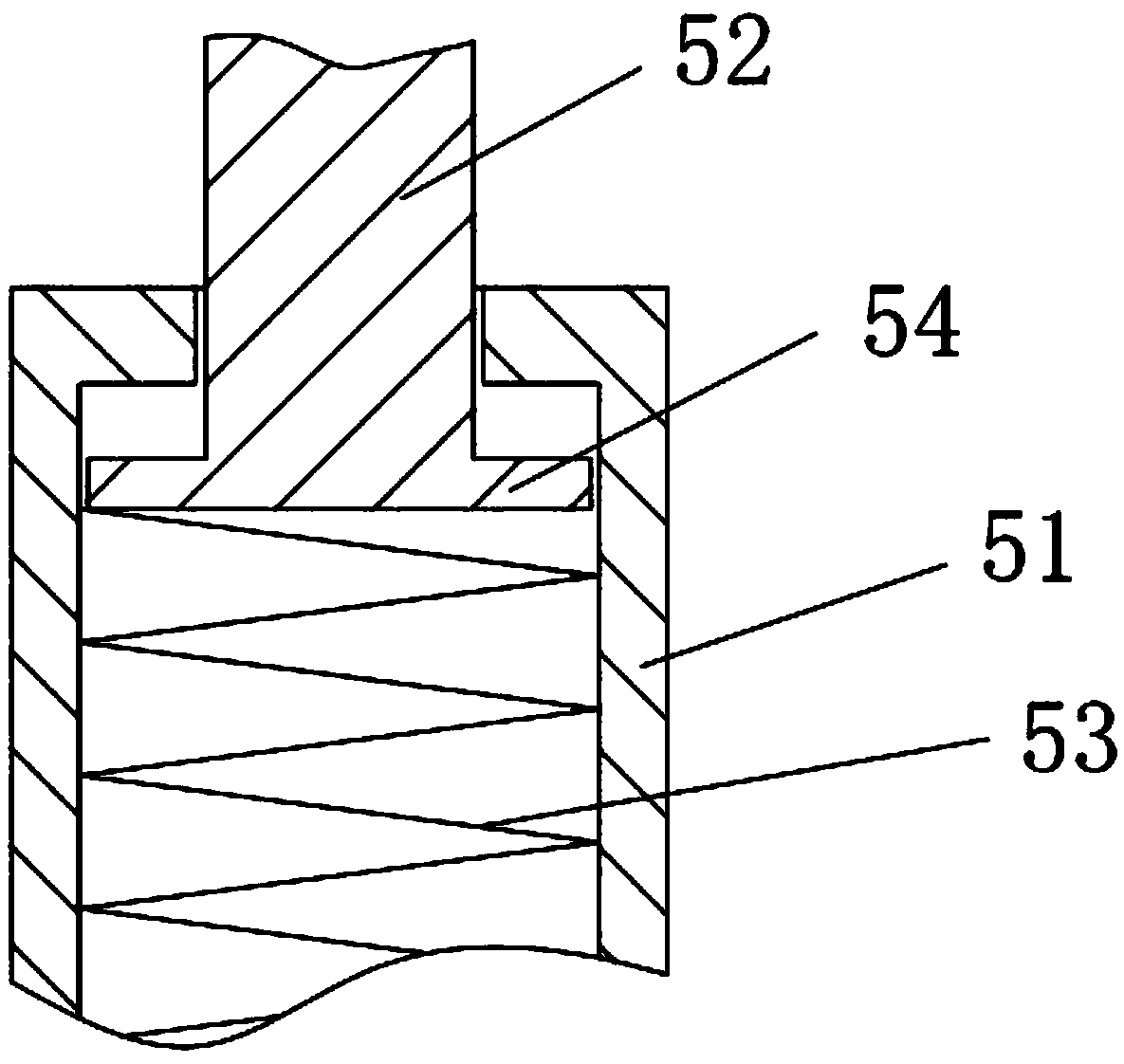
[0025] Figure 1 to Figure 3 Shown is a strip winding mechanism provided by the present invention, including a machine base 1, a fixed base 2 and an air expansion shaft 3; a rotating shaft 4 is rotatably supported on the machine base 1, and one end of the rotating shaft 4 is connected to the air expansion shaft The shaft 3 is fixedly connected; the fixed seat 2 is located below the air expansion shaft 3, and the fixed seat 2 includes an elastic support leg 5 and a fixed plate 6 fixed on the elastic support leg; the fixed plate 6 is also rotatably supported by a bracket roll 7.

[0026] The base is a frame structure, and the rotating shaft 4 is fixedly installed on the machine base 1 through the bearing seat, and rotates on the machine base 1; the air expansion shaft 3 and the rotating shaft 4 are connected and fix...


PUM


Abstract

The invention discloses a belt material rolling mechanism and relates to the technical field of finished belt material rolling. The belt material rolling mechanism comprises a machine seat, a fixing seat and an air expansion shaft. A rotating shaft is rotatably arranged on the machine seat in a supported manner. One end of the rotating shaft is fixedly connected with the air expansion shaft. The fixing seat is located below the air expansion shaft and comprises elastic support legs and a fixing plate, wherein the fixing plate is fixed to the elastic support legs. A carrying roller is rotatablysupported by the fixing plate. By means of the belt material rolling mechanism, the rolling effect of a belt material is greatly improved; and meanwhile, by means of the air expansion shaft, rollingshafts of different diameters can be fixed, and the rolling scope can be wider.

Description

technical field [0001] The present invention relates to the technical field of winding finished strips, in particular to a winding mechanism for strips. Background technique [0002] As a common blank, strip is widely used in various fields. Due to the long length of the strip, in order to facilitate the transportation of the strip, the finished strip is generally wound into a disk during the production process of the strip, so that the strip material can be easily taken and the storage time of the strip is reduced. space taken up. But the existing winding device has only one winding roller. After the winding is completed, the strip on the winding roller will be taken off before the winding can be continued. It takes a lot of time to roll the roll, so that the efficiency of winding is greatly reduced. Contents of the invention [0003] The object of the present invention is to provide a strip winding mechanism to solve the above problems. [0004] In order to achieve t...

Claims


Application Information

Patent Timeline
Patent Type & Authority Applications(China)
IPC IPC(8): B65H18/08
CPCB65H18/08
Inventor 陈作伟
Owner 四川高德特科技有限公司
Learn More