
Automatic electric wire winding plate

An automatic winding and wire technology, applied in the field of wire reels, can solve the problems of low wire collection efficiency, labor consumption of operators, and confusion in wire collection, so as to achieve high wire collection efficiency, reduce labor intensity and improve wire collection efficiency. Effect

Pending Publication Date: 2019-02-22
GUANGDONG POWER GRID CO LTD +1
View PDF0 Cites 3 Cited by
  • Summary
  • Abstract
  • Description
  • Claims
  • Application Information

AI Technical Summary

Problems solved by technology

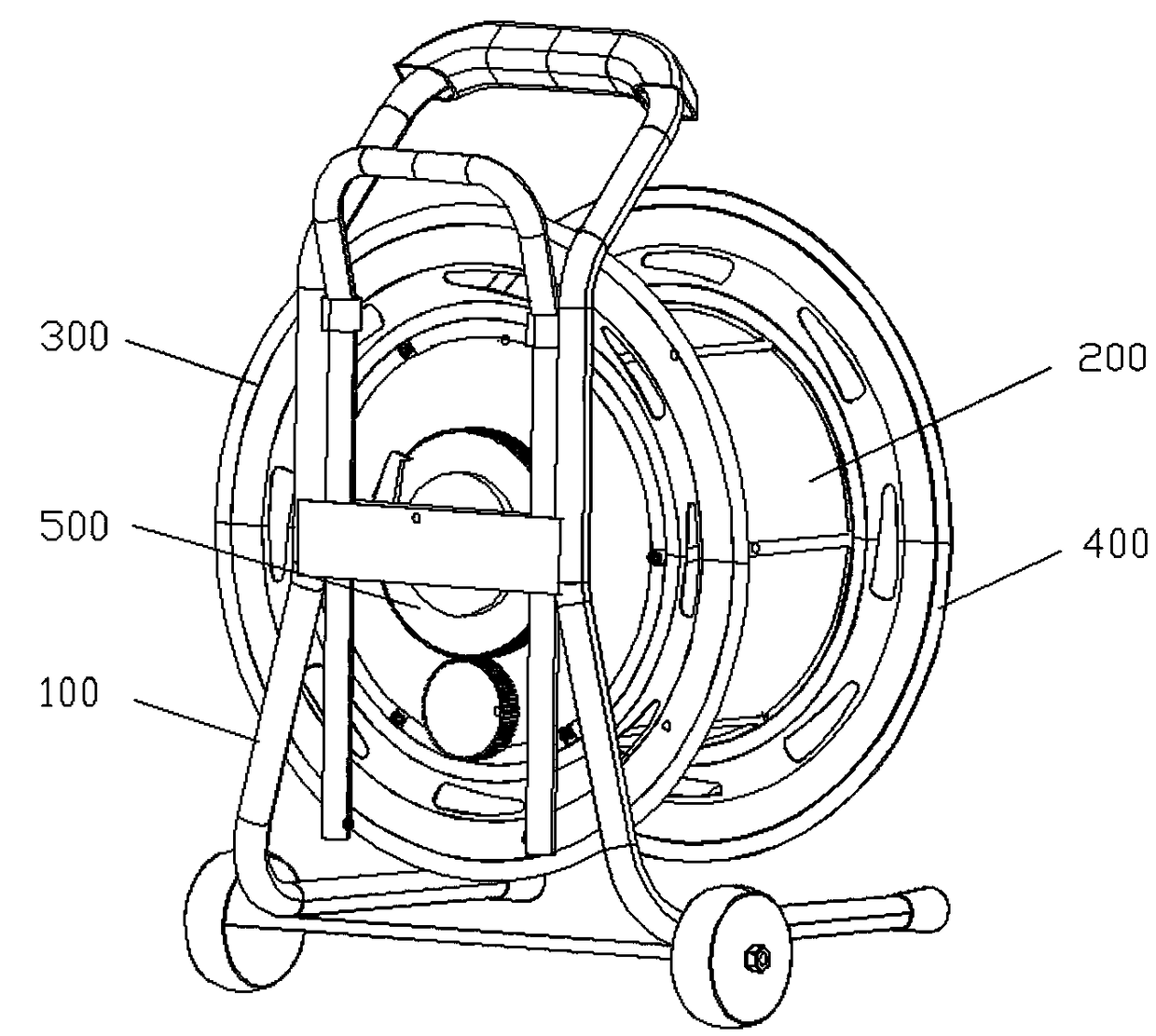
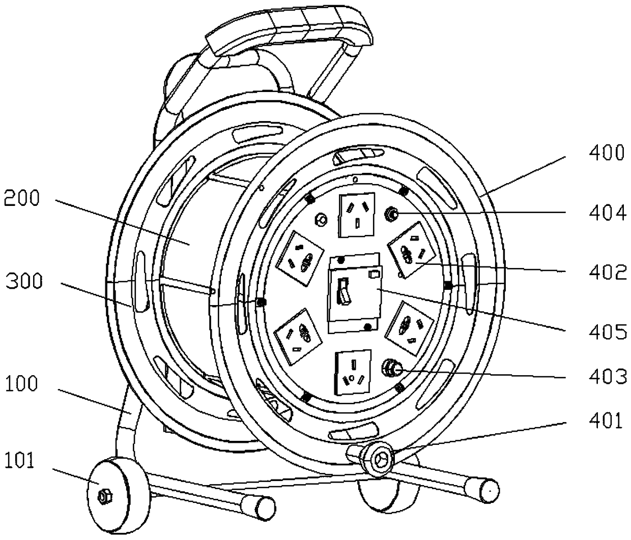
[0005] The purpose of the present invention is to provide an automatic winding wire reel to solve the technical problems in the prior art that the moving wire reel adopts the manual winding method, which consumes the physical strength of the workers, the winding efficiency is low, and the winding is chaotic.

Method used


Image

  • Automatic electric wire winding plate
  • Automatic electric wire winding plate
  • Automatic electric wire winding plate

Examples


Embodiment Construction

[0037] The technical solutions of the present invention will be clearly and completely described below in conjunction with the accompanying drawings. Apparently, the described embodiments are some of the embodiments of the present invention, but not all of them. Based on the embodiments of the present invention, all other embodiments obtained by persons of ordinary skill in the art without making creative efforts belong to the protection scope of the present invention.

[0038] In the description of the present invention, it should be noted that the terms "center", "upper", "lower", "left", "right", "vertical", "horizontal", "inner", "outer" etc. The indicated orientation or positional relationship is based on the orientation or positional relationship shown in the drawings, and is only for the convenience of describing the present invention and simplifying the description, rather than indicating or implying that the referred device or element must have a specific orientation, ...


PUM


Abstract

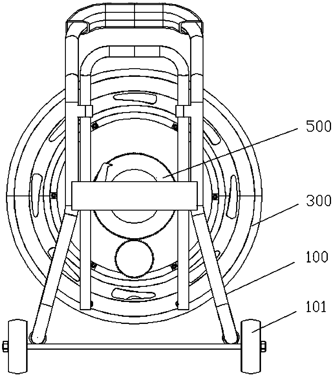
The invention provides an automatic electric wire winding plate, and relates to the technical field of electric wire plates. The automatic electric wire winding plate comprises a support, a wire winding roller, a first baffle plate and an automatic wire winding assembly, wherein the wire winding roller is connected onto the support; the first baffle plate is connected to the inner side end of thewire winding roller; one end of the automatic wire winding assembly is connected onto the support; the other end of the automatic wire winding assembly is connected onto the first baffle plate; and the automatic wire winding assembly can drive the first baffle plate to rotate so as to enable the first baffle plate to drive the wire winding roller to automatically wind a wire. The technical problems that in the prior art, a movable electric wire plate adopts a manual wire winding manner, so that the physical power of operating personnel is wasted, the wire winding efficiency is low, and the wire is winded disorderly are solved. According to the automatic electric wire winding plate provided by the invention, the automatic wire winding assembly is connected between the first baffle plate andthe wire winding roller and is utilized for driving the first baffle plate to move, so that the wire winding roller is driven to wind the wire automatically, the wire winding efficiency is high, andthe wire is winded in order.

Description

technical field [0001] The invention relates to the technical field of wire reels, in particular to an automatic winding wire reel. Background technique [0002] At the job site, operation and maintenance personnel need to enter various maintenance locations to carry out maintenance operations. At this time, they need to carry a mobile wire tray to use the mobile wire tray to provide power for the electrical equipment on the job site to ensure that the maintenance work is carried out. [0003] At present, there are many kinds of specifications of mobile wire reels used on site, such as: two-core wires, three-core wires, etc. The length of the wires is 30 meters or 50 meters. The above-mentioned specifications of the wires provide a great convenience. [0004] In the above-mentioned prior art, the mobile wire reel adopts a hand-cranked winding method when taking up the wires. With this winding method, when the length of the wire is relatively long, the operator needs to spen...

Claims


Application Information

Patent Timeline
IPC IPC(8): B65H75/48B65H75/42
CPCB65H75/425B65H75/48B65H2701/34
Inventor 张林海韩金尅邱凌枫朱丽媛李镕东余科锋
Owner GUANGDONG POWER GRID CO LTD
Learn More