Optical cable take-up machine with anti-jumping function

A wire take-up and functional technology, applied in the direction of conveying filamentous materials, thin material handling, transportation and packaging, etc., can solve the problems of increasing the damage of optical fibers, looping, damage to optical cables, etc. The probability of the disc, the increase of the contact area, and the effect of improving the efficiency of the wire take-up

Inactive Publication Date: 2015-09-02
成都亨通光通信有限公司
View PDF16 Cites 2 Cited by
  • Summary
  • Abstract
  • Description
  • Claims
  • Application Information

AI Technical Summary

Problems solved by technology

[0003] During the long-distance laying of optical cables, due to the influence of various factors, some of the pulled out optical cables need to be recycled. In the prior art, due to the distance factor, the optical cables are usually manually rotated when the cable is pulled to achieve the optical cable on the cable reel. Layers are stacked on top of each other, and the strength of the cable will increase with the increase of the distance when it is recovered, so some parts of the optical cable may be partially damaged due to the concentration of stress. The surge phenomenon occurs at the outlet of the reel, which makes the middle part of the optical cable and the end of the optical cable circle, that is, it is very likely to cause the bending radius of the optical cable to be less than 15 to 20 times its outer diameter, which increases the possibility of damage to the optical fiber. , at the same time, the work intensity of manually rotating the cable drum is high, and the work efficiency of the workers is low

Method used


Image

  • Optical cable take-up machine with anti-jumping function
  • Optical cable take-up machine with anti-jumping function

Examples


Embodiment 1

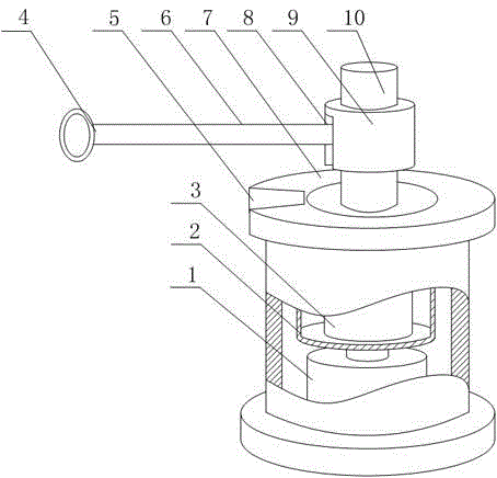
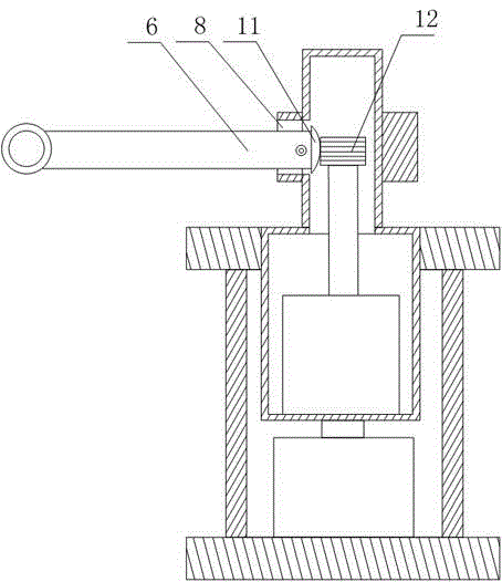
[0021] Such as figure 1 and figure 2 As shown, this embodiment includes a hollow cable reel 7 and a motor 1 fixed in the cable reel 7, the output end of the motor 1 is connected with a positioning cylinder 2, the upper end of the positioning cylinder 2 penetrates the upper end surface of the cable reel 7, and A cylinder 3 is installed in the positioning cylinder 2, and a rotating cylinder 10 communicating with it is fixed on the upper end surface of the positioning cylinder 2. The side wall of the rotating cylinder 10 is provided with a rectangular gap, and is hinged in the gap. There is a guide rod 6, a plurality of annular teeth 12 are arranged on the output end of the cylinder 3, one end of the guide rod 6 is provided with sector teeth 11 matched with the ring teeth 12, and a guide ring 4 is installed at the other end of the guide rod 6; it also includes The fixed block 9 fixed on the outer wall of the rotating cylinder 10 has a movable groove 8 communicating with the gap...


PUM


Abstract

The invention discloses an optical cable take-up machine with an anti-jumping function. The optical cable take-up machine with the anti-jumping function comprises a cable reel and a motor, wherein the output end of the motor is connected with a positioning drum, the upper end of the positioning drum penetrates through the upper end surface of the cable reel, an air cylinder is installed in the positioning drum, a rotary drum communicated with the internal portion of the positioning drum is fixedly arranged on the upper end surface of the positioning drum, a rectangular notch is formed in the side wall of the rotary drum, a guide rod is hinged in the notch, a plurality of annular teeth are arranged on the output end of the air cylinder, sector-shaped teeth matched with the annular teeth are arranged at one end of the guide rod, and a guide ring is installed at the other end of the guide rod. by limiting an optical cable through the guide ring, the optical cable can be prevented from jumping during movement, the upward and downward movement of the guide rod can buffer the oscillating amplitude of the optical cable, the optical cable is guaranteed to be kept in a relatively stable state after the optical cable enters the cable reel, the optical cable at each layer on the cable reel is enabled to be more uniformly distributed, two adjacent turns of optical cable can be closely fit together, the space on the cable reel is effectively utilized and the take-up efficiency of the optical cable is improved.

Description

technical field [0001] The invention relates to the field of optical cable laying, in particular to an optical cable take-up machine with the function of preventing wire jumping. Background technique [0002] In daily life, optical fibers are used for long-distance information transmission because the loss of light in optical fibers is much lower than that of electricity in wires. Most optical fibers must be covered by several layers of protective structures before use. The coated cable is called an optical cable. The protective layer and insulating layer on the outer layer of the optical fiber can prevent the surrounding environment from harming the optical fiber, such as water, fire, electric shock, etc. . [0003] During the long-distance laying of optical cables, due to the influence of various factors, some of the pulled out optical cables need to be recycled. In the prior art, due to the distance factor, the optical cables are usually manually rotated when the cable i...

Claims


Application Information

Patent Timeline
Patent Type & Authority Applications(China)
IPC IPC(8): B65H54/30B65H57/06B65H75/28
Inventor 孙义兴王耀明许建国彭志勇刘东李涛
Owner 成都亨通光通信有限公司
Why Eureka
Try Eureka