Expander-compressor unit

a compressor unit and compressor technology, applied in the direction of positive displacement liquid engine, lighting and heating apparatus, domestic cooling apparatus, etc., can solve the problem of cost increase, and achieve the effect of suppressing cost and preventing an increase in parts coun

Inactive Publication Date: 2010-10-28
PANASONIC CORP
View PDF39 Cites 20 Cited by
  • Summary
  • Abstract
  • Description
  • Claims
  • Application Information

AI Technical Summary

Benefits of technology

[0011]In the above-mentioned expander-compressor unit, it is conceivable that the shaft is provided with an upper eccentric portion for the compression mechanism or the expansion mechanism, an intermediate eccentric portion for the oil pump, and a lower eccentric portion for the expansion mechanism or the compression mechanism. Usually, the compression mechanism and the expansion mechanism each have a bearing member for supporting a portion of the shaft inside an eccentric portion in order to prevent the runout of the eccentric portion. Thus, in the case where the eccentric portions are provided as mentioned above, the shaft may be divided into two portions at a position above the intermediate eccentric portion, for example, from the viewpoint of inserting the shaft into the bearing member of the upper-located mechanism. The intermediate eccentric portion and the lower eccentric portion remain on the lower portion of the shaft. Therefore, as a measure to insert the lower portion of the shaft into the bearing member of the lower-located mechanism, it can be considered to allow the intermediate eccentric portion to be mounted later or further to divide the lower portion of the shaft into two portions. However, such measures increase parts count, resulting in cost increase. Hence, the present inventors have conceived a configuration that allows the lower portion of the shaft having the intermediate eccentric portion and the lower eccentric portion to be inserted into the bearing member.
[0023]Furthermore, since the diameter of the intermediate eccentric portion of the lower shaft is equal to or less than that of the portion of the lower shaft supported by the bearing member in the configuration of the present invention, the lower shaft can be inserted into the bearing member as is even when holding the intermediate eccentric portion. Thereby, it is possible to provide the lower shaft with the intermediate eccentric portion and the lower eccentric portion integrally. Moreover, there is no need to divide the lower shaft. As a result, it is possible to prevent an increase in the parts count and suppress the cost.

Problems solved by technology

However, such measures increase parts count, resulting in cost increase.

Method used


Image

  • Expander-compressor unit
  • Expander-compressor unit
  • Expander-compressor unit

Examples


Embodiment Construction

[0034]Hereinbelow, embodiments of the present invention will be described with reference to the accompanying drawings.

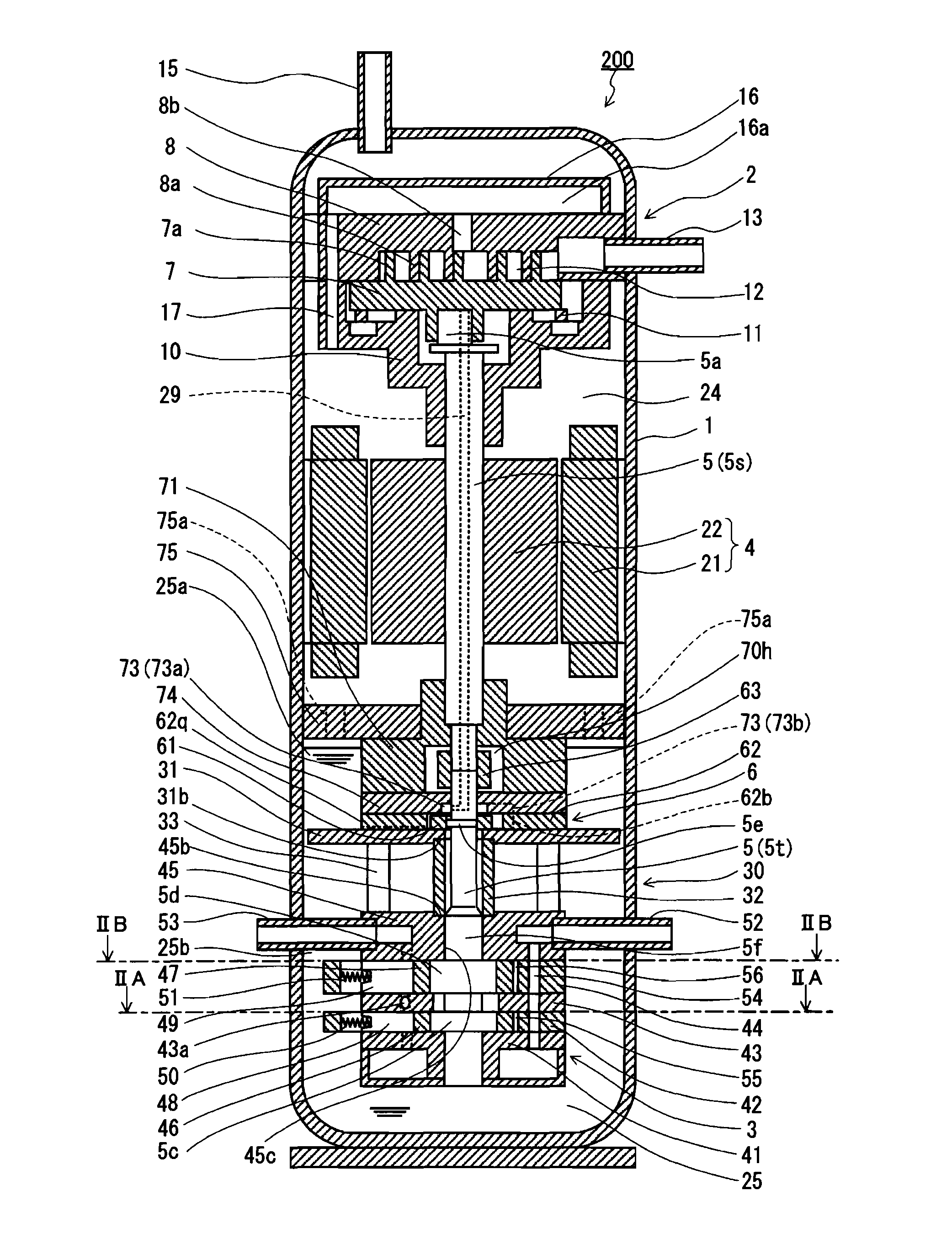
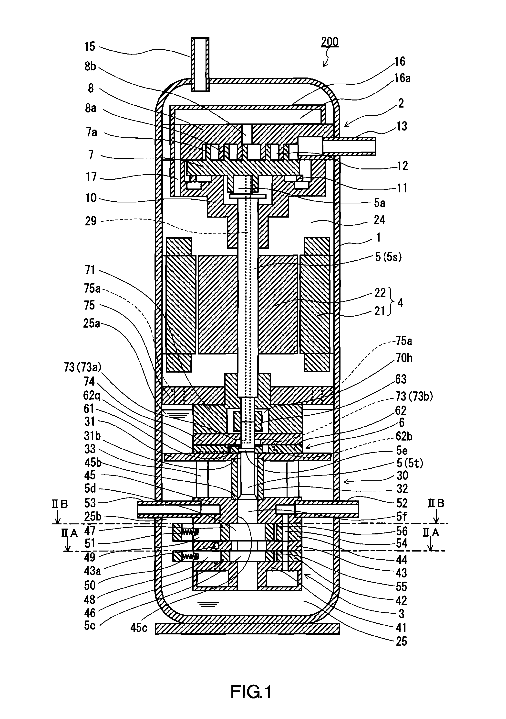
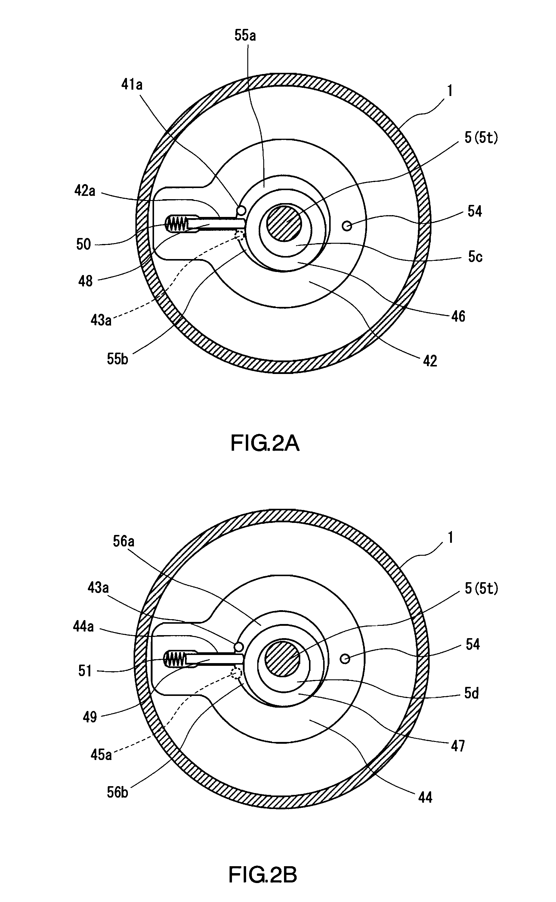
[0035]FIG. 1 is a vertical cross-sectional view of one expander-compressor unit according to an embodiment of the present invention. FIG. 2A is a transverse cross-sectional view of the expander-compressor unit shown in FIG. 1 taken along the line IIA-IIA. FIG. 2B is a transverse cross-sectional view of the expander-compressor unit shown in FIG. 1 taken along the line IIB-IIB. FIG. 3 is a partially enlarged view of FIG. 1.

[0036]As shown in FIG. 1, an expander-compressor unit 200 includes a closed casing 1, a scroll-type compression mechanism 2 disposed at an upper position in the closed casing 1, a two-stage rotary-type expansion mechanism 3 disposed at a lower position in the closed casing 1, a motor 4 disposed between the compression mechanism 2 and the expansion mechanism 3, an oil pump 6 disposed between the motor 4 and the expansion mechanism 3, a shaft 5 couplin...


PUM


Abstract

An expander-compressor unit (200) includes a closed casing (1), a compression mechanism (2), an expansion mechanism (3), a shaft (5), and an oil pump (6). The shaft (5) includes an upper shaft (5s) provided with an upper eccentric portion (5a) for the compression mechanism (2), and a lower shaft (5t) provided with lower eccentric portions (5d and 5c) for the expansion mechanism (3) and an intermediate eccentric portion (5e) for the oil pump (6). The expansion mechanism (3) has an upper bearing member (45) for supporting a supported portion (5f) of the lower shaft (5t) located immediately above the lower eccentric portion (5d). The intermediate eccentric portion (5e) has a diameter equal to or less than that of the supported portion (5f).

Description

TECHNICAL FIELD[0001]The present invention relates to an expander-compressor unit including a compression mechanism for compressing a fluid and an expansion mechanism for expanding the fluid.BACKGROUND ART[0002]As an example of fluid machines having an expansion mechanism and a compression mechanism, an expander-compressor unit conventionally has been known. FIG. 9 is a vertical cross-sectional view of an expander-compressor unit described in JP 2005-299632 A.[0003]An expander-compressor unit 103 includes a closed casing 120, a compression mechanism 121, a motor 122, and an expansion mechanism 123. A shaft 124 couples the motor 122, the compression mechanism 121, and the expansion mechanism 123. The expansion mechanism 123 recovers power from a working fluid (such as a refrigerant) expanding, and provides the recovered power to the shaft 124. Thereby, the power consumption of the motor 122 for driving the compression mechanism 121 is reduced, and the coefficient of performance of a ...

Claims


Application Information

Patent Timeline
Patent Type & Authority Applications(United States)
IPC IPC(8): F04C23/02F25D9/00F01C13/04F01C21/04F04C18/32
CPCF01C13/04F04C18/0215F04C18/356F04C2240/809F04C23/008F04C29/025F04C23/005
Inventor WADA, MASANOBUSHIOTANI, YUOYAGI, SHINGOTAKAHASHI, YASUFUMIOGATA, TAKESHI
Owner PANASONIC CORP
Why Eureka
Try Eureka