Distributed synchronization and timing system

a timing system and synchronization technology, applied in the direction of digital transmission, generating/distributing signals, instruments, etc., can solve the problems of severe restrictions, insufficient specification, and the inability to accurately time-stamp

Inactive Publication Date: 2009-09-03
CHRONOLOGIC PTY LTD
View PDF18 Cites 86 Cited by
  • Summary
  • Abstract
  • Description
  • Claims
  • Application Information

AI Technical Summary

Benefits of technology

[0037]It is another object of the invention to retain the advantages of USB while supplementing the USB specification, including the ability to operate multiple devices via a tiered star architecture (up to a current total of 127 devices), hot-swap capability, automatic enumerati

Problems solved by technology

The specification does not sufficiently address this issue.
This is a severe restriction when there is a need to synchronize devices at megahertz levels and above.
This unfortunately means that the available USB bandwidth can be used up before the maximum number of devices has been connected.
This approach also places on the host the great computational burden of keeping 127 devices synchronized to the host by means of software, yet still fails to address maintaining synchrony between the devices as to the host the individual devices represent separate processes.
However, the specification does not address the potential problems of synchronizing 100 USB-speaker pairs.
Further, neither a frequency lock to 1 kHz or better stability nor high accurate phase control is disclosed.
However these approaches do not measure the frequency of a periodic data structure contained within the USB data traffic for determination of the absolute frequency of the master clock in the USB Host Controller, and in some cases rely on the provision of an additional counter in the host.
This document, however, relates to the synchronization of th

Method used


Image

  • Distributed synchronization and timing system
  • Distributed synchronization and timing system
  • Distributed synchronization and timing system

Examples


first embodiment

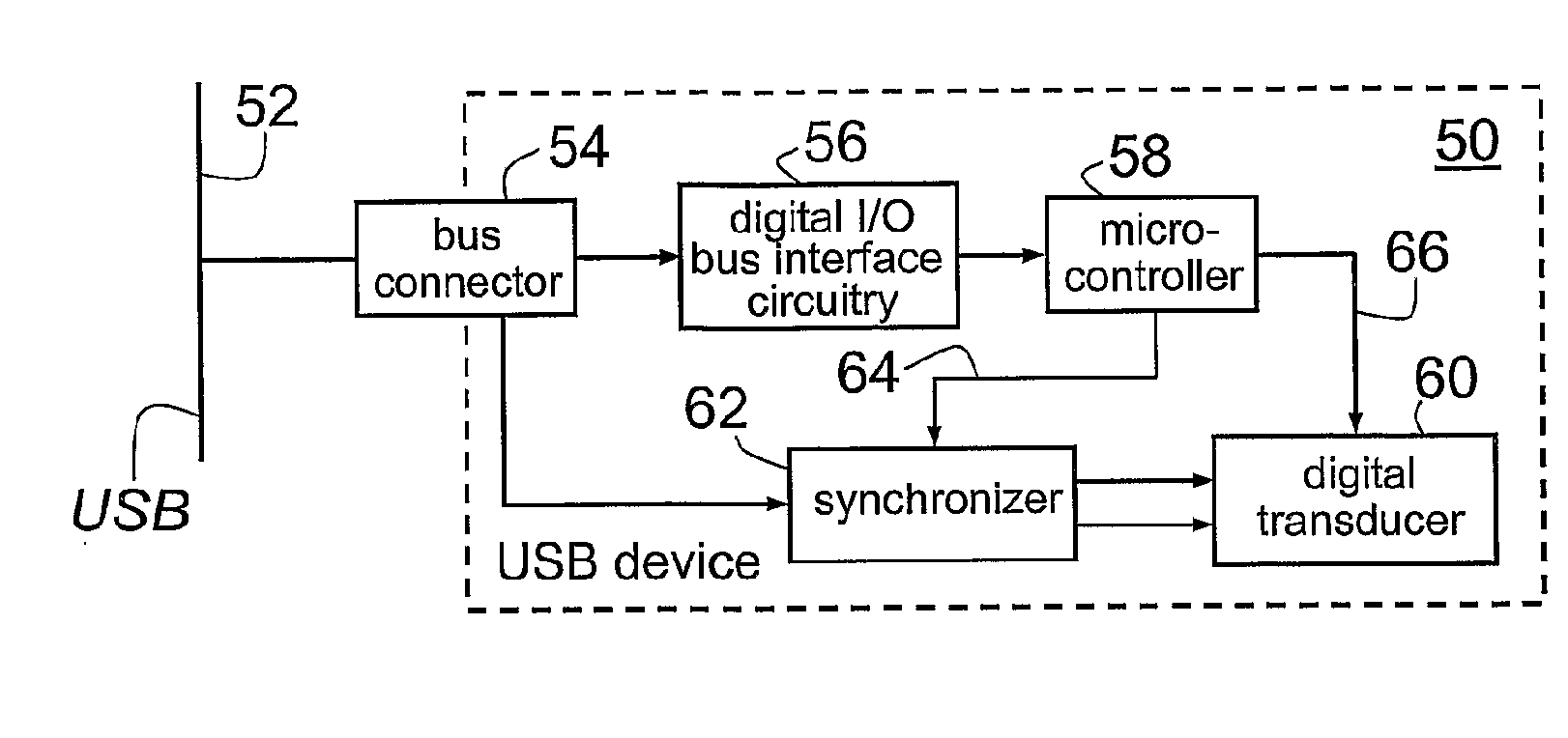
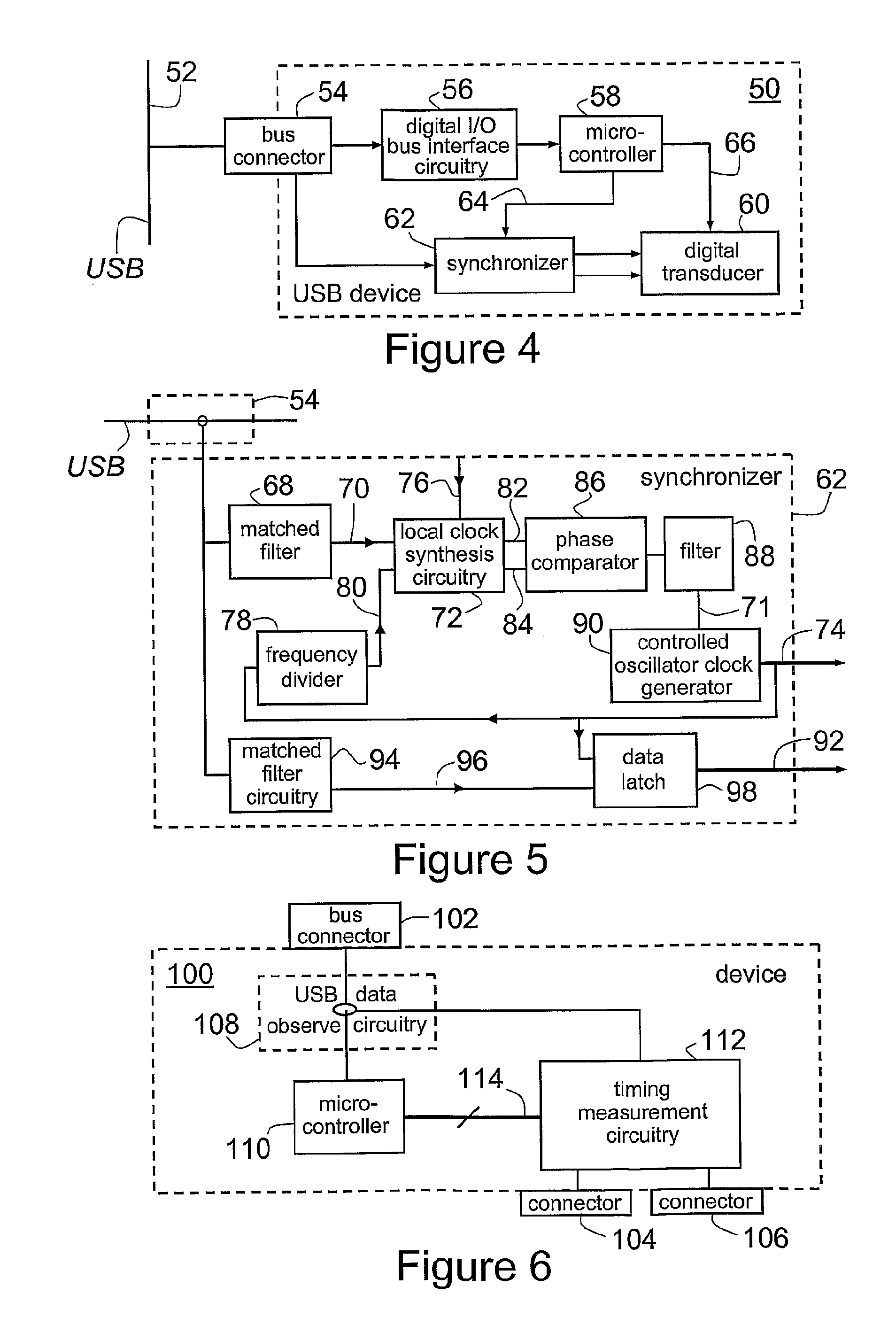
[0121]A USB device according to the present invention is shown schematically at 50 in FIG. 4, with a USB 52. In this embodiment, clock synchronization information to allow the local clock of the USB device 50 to be frequency controlled to an arbitrary degree is passed to the USB device by a carrier signal (described below) that is then decoded from the USB data stream.

[0122]Referring to FIG. 4, USB device 50 includes a bus connector 54, digital I / O bus interface circuitry 56, a microcontroller 58, a digitally controlled transducer 60 and synchronization circuitry in the form of synchronizer 62 (described in greater detail below). The digital I / O bus interface circuitry 56 acts as a transceiver for USB data detected at bus connector 54, passing the USB data to microcontroller 58. The microcontroller 58 provides information 64 to synchronizer 62 for accurate frequency synthesis and a direct control channel 66 to digitally controlled transducer 60.

[0123]The carrier signal referred to a...

second embodiment

[0129]As discussed above, the SOF packet broadcast occurs at a nominal frequency of 1 kHz but the actual frequency of this signal is determined by the accuracy of the USB Host Controller clock. A USB device 100 according to the invention employs a method for determining the effective clock rate of the USB Host Controller by accurately measuring the frequency of the SOF packet. This signal can then be considered a carrier for information about the Host Controller clock rate and the carrier signal is broadcast to all connected USB devices. The carrier signal embedded in the normal USB protocol is thus decoded and its frequency measured to determine the effective clock rate of the USB Host Controller clock.

[0130]Thus, FIG. 6 is a schematic diagram of a device 100 for synchronizing a USB according to a second embodiment of the invention, which includes a USB bus connector 102 for connection to a USB. Device 100 has a first connector 104 for receiving an external reference clock signal, ...

third embodiment

[0135]FIG. 8 is a schematic diagram of a USB system 140 according to the present invention, in which a personal computer 142 with a USB Host Controller 144 is attached to a single USB device 146 at a USB 148. The USB device 144 contains timing measurement circuitry 150 (as per timing measurement circuitry 112 of FIG. 7) to measure repetitive carrier signal frequency using an internal reference clock (comparable to local reference clock 130 of FIG. 7) to an arbitrary degree. Thus, in this embodiment the absolute frequency of the clock carrier signal of the USB Host Controller 144 is determined by means of circuitry (i.e. the timing measurement circuitry 150) contained solely within a USB device. Further, it will be apparent to those skilled in the art that, although this embodiment includes a personal computer, alternative similar embodiments may instead include any device, such as a personal digital assistant (PDA) or mobile communication device, that contains a USB host controller ...


PUM


Abstract

A method and apparatus for controlling the phase and frequency of the local clock of a USB device, the apparatus comprising circuitry for observing USB traffic and decoding from the USB traffic a periodic data structure containing information about the frequency and phase of a distributed clock frequency, and phase and circuitry for receiving the periodic data structure and generating from at least the periodic data structure a local clock signal locked in both frequency and phase to the periodic data structure. The circuitry for receiving the periodic data structure and generating the local clock signal can generate the local clock signal with a frequency that is a non-integral multiple of a frequency of the periodic data structure.

Description

RELATED APPLICATION[0001]This application is based on and claims the benefit of the filing date of U.S. application No. 60 / 773,537 filed 15 Feb. 2006, the content of which is incorporated herein by reference in its entirety.FIELD OF THE INVENTION[0002]The present invention relates to a method and apparatus for providing a distributed synchronization and timing system, of particular but by no means exclusive use in providing clocks, data acquisition and control of test and measurement equipment, instrumentation interfaces and process control equipment, synchronized to an essentially arbitrary degree.BACKGROUND OF THE INVENTION[0003]The USB specification is intended to facilitate the interoperation of devices from different vendors in an open architecture. USB data is encoded using differential signalling (viz. two wires transfer the information) in the form of the difference between the signal levels of those two wires. The USB specification is intended as an enhancement to the PC ar...

Claims


Application Information

Patent Timeline
IPC IPC(8): G06F1/04G06F13/00G06F1/12G06F17/30
CPCG06F1/12G06F1/14
Inventor FOSTER, PETER GRAHAMKOUZNETSOV, ALEXVLASENKO, MYKOLA
Owner CHRONOLOGIC PTY LTD
Why Eureka
Try Eureka