Electrical connector with improved contacts

a technology of electric connectors and contacts, applied in the direction of fixed connections, coupling device connections, coupling protective earth/shielding arrangements, etc., can solve the problems of difficult to bend the wings, difficult to locate the tips of the contacts and the main bodies of the contacts on the same plane, etc., to prevent jumping outwards of the contact, the effect of improving the conta

Inactive Publication Date: 2010-06-15
HON HAI PRECISION IND CO LTD
View PDF12 Cites 20 Cited by
  • Summary
  • Abstract
  • Description
  • Claims
  • Application Information

AI Technical Summary

Benefits of technology

[0008]Accordingly, the object of the present invention is to provide an electrical connector with improved contacts for soldering conveniently and preventing jumping outwards thereof from an insulative housing.

Problems solved by technology

However, it's difficult to bend the wings when the contact becomes thicker.
However, when the contacts are insert-molded within the housing, it's difficult to make tips of the contacts and main bodies of the contacts locate on a same plane.

Method used


Image

  • Electrical connector with improved contacts
  • Electrical connector with improved contacts
  • Electrical connector with improved contacts

Examples


Embodiment Construction

[0016]Reference will now be made to the drawing figures to describe the present invention in detail.

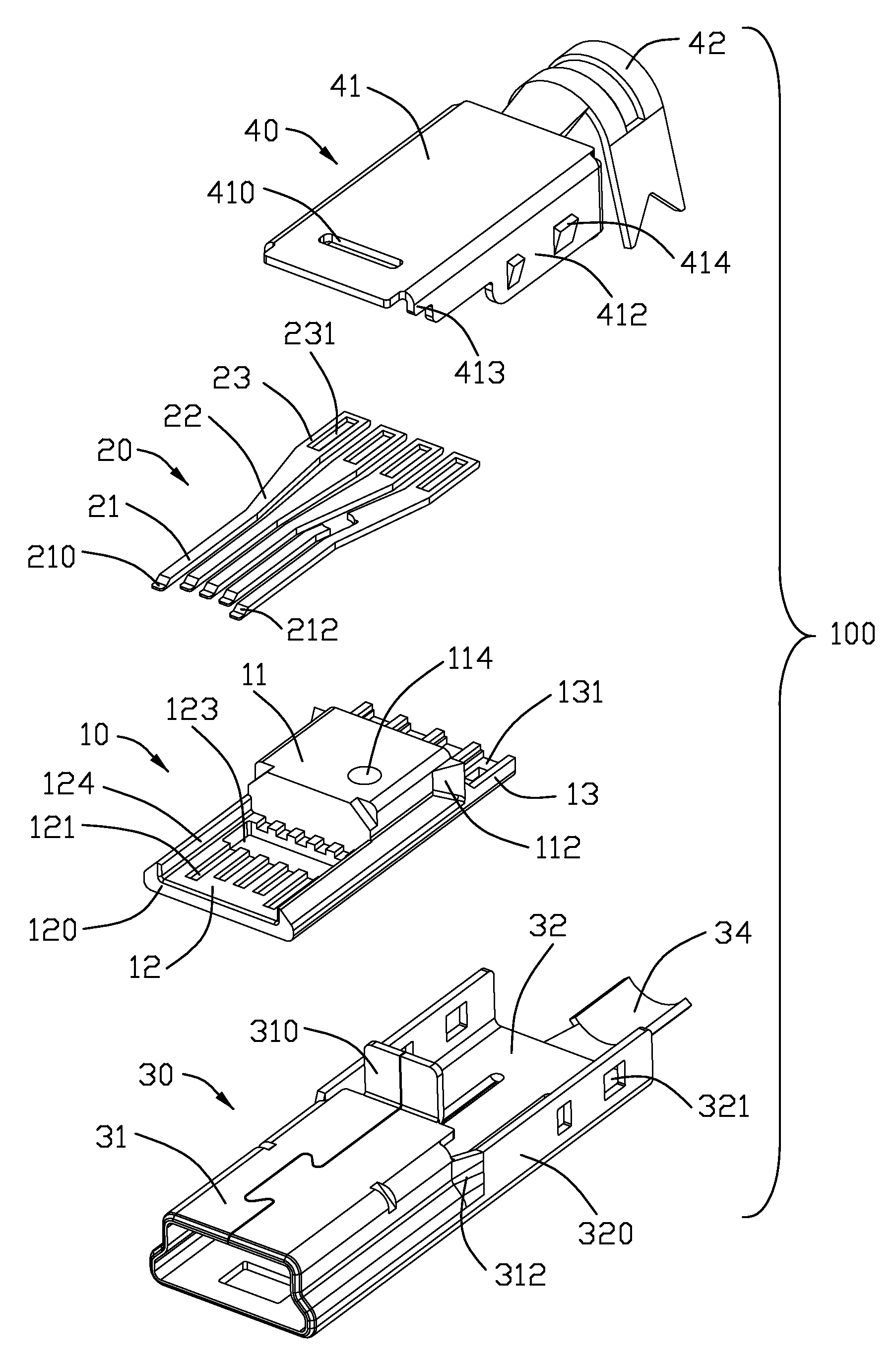
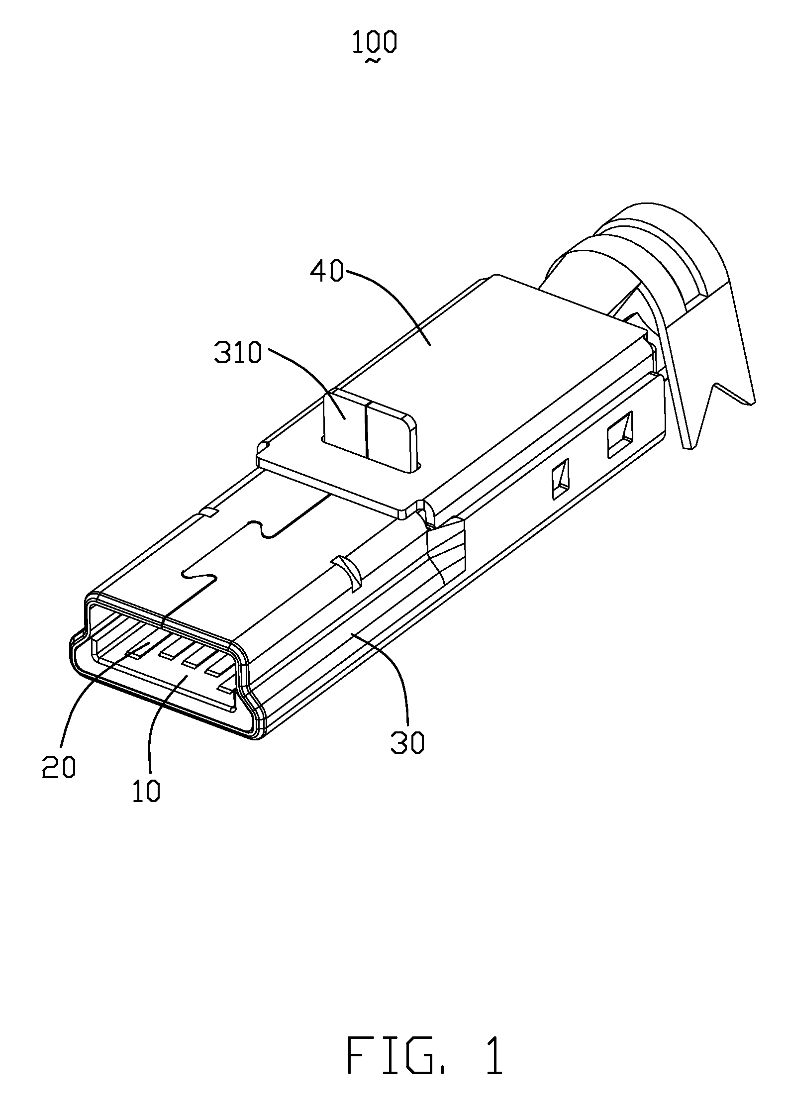
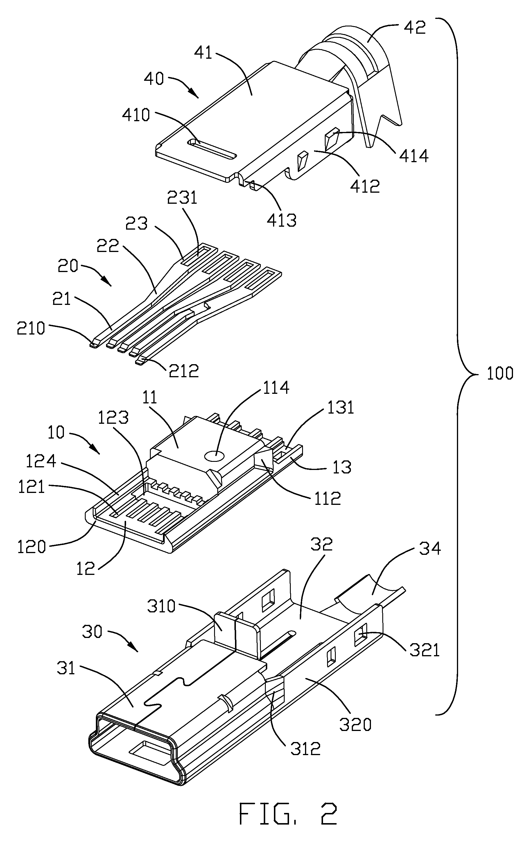
[0017]Referring to FIGS. 1-2, an electrical connector 100 in accordance with the present invention comprises an insulative housing 10, a contact set 20 molded in the insulative housing 10, a bottom shell 30 attached to the housing 10 and a top shell 40 assembled to a back portion of the bottom shell 30 along an up-to-down direction.

[0018]Referring to FIGS. 2-4, the insulative housing 10 of the electrical connector 100 comprises a base portion 11, a U-shape tongue 12 extending forwardly from the base portion 11 along a mating direction and a supporting portion 13 extending rearwards from the base portion 11. The base portion 11 defines a pair of block portion 112 extending outwards from back sections of lateral sides thereof, the block portions 112 are connected with the supporting portion 113. A circular hole 114 is defined in the base portion 11, and upper segment of hole 114 is smal...


PUM


Abstract

An electrical connector (100) comprises an insulative housing (10), a shell encapsulating the insulative housing and a plurality of contacts (20) received in the housing abreast. The insulative housing defines a tongue (12), a plurality of passageways (121) and receiving grooves (131), the passageways extending to the tongue, the tongue has a stopping portion (126) in the front of each passageway. A cavity is defined below each stopping portion and communicated with the passageway. Each contact has a contacting portion (21) and a tail portion (23) wider than the contacting portion, the contacting portions are received in a corresponding passageways with the tail portions received in a corresponding receiving grooves. Each contacting portion defines a tab (210) protruding forwardly from a bottom surface thereof, the tab is received in the cavity and protected by the stopping portion (126); each tail portion is stamped downwards to form a notch (231) receiving wires and soldering with the wires.

Description

BACKGROUND OF THE INVENTION[0001]1. Field of the Invention[0002]The present invention generally relates to an electrical connector, and more particularly to an electrical connector with improved contacts.[0003]2. Description of Related Art[0004]Nowadays, miniaturization of electronic devices, such as notebooks, PDA, etc has become a trend such that the dimension and size of electronic connectors used therein have to be modified and reduced so as to meet the requirements.[0005]CN Patent No. 1049072C issued to Tian on Feb. 2, 2000 discloses a mini USB connector. The mini USB connector comprises an insulative housing, a group of contacts received in the housing and a metallic shielding assembled to the housing. Each contact defines a tail portion with a pair of wings extending laterally, the wings are bent toward each other to receive one of wires therein, to prevent solder from flowing. However, it's difficult to bend the wings when the contact becomes thicker.[0006]Said contacts are ...

Claims


Application Information

Patent Timeline
Patent Type & Authority Patents(United States)
IPC IPC(8): H01R27/00H01R12/55
CPCH01R4/02H01R24/62H01R2107/00
Inventor YUAN, XINLIU, SU-FENGLAI, CHIN-TE
Owner HON HAI PRECISION IND CO LTD
Why Eureka
Try Eureka