

Cable winding and unwinding device
A technology for taking up and paying off wires and cables, which is applied in the field of cable wire take-up and pay-off devices, can solve the problems of poor generality of pay-off spools, etc., to ensure the safety of pay-offs, reduce the time of replacing wire spools, and improve the effect of versatility.
- Summary
- Abstract
- Description
- Claims
- Application Information
AI Technical Summary
Problems solved by technology
Method used
Image

Examples
Embodiment 1
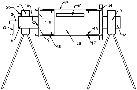
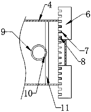
[0025] This embodiment, as the best embodiment of the present invention, discloses a cable retractable wire, the specific structure is as follows: figure 1 As shown, it includes a left frame 1 and a right frame 2. The left frame 1 is rotatably provided with a connected rotating shaft 3 and a left base 4, and a turntable 5 is provided for rotation in the left pedestal 4. The right side is provided with an Archimedes spiral groove 8, the left side is provided with a transmission gear 11, and three sliders 6 are slidably arranged on the left base 4, and between the sliders 6 and the turntable 5, Archimedes The spiral groove 8 is meshed with the locking teeth 7; the outer circumference of the left base 4 is evenly provided with a plurality of adjustment holes 9, and an adjustment gear 10 is arranged to rotate in the adjustment hole 9, and the adjustment gear 10 is connected with the rotating disc 5. The transmission gear 11 is meshed, and the adjustment gear 10 is provided with an...
Embodiment 2
[0027] In this embodiment, as another preferred embodiment of the present invention, six sliders 6 are arranged on the left base 4 .
[0028] The invention rotates the adjusting gear through the inner hexagonal bolt to drive the turntable to rotate, and the turntable drives the slider to slide on the left base, thereby changing the distance between the support rods, adjusting the size of the bobbin, and after the adjustment is in place, the support rod is inserted into the right base In the support hole, firstly, you only need to wrap the thread end on the support rod, and then turn the shaft through the handle to realize fast take-up. into the support hole, and then fine-tune the tension coil to perform the payout; the size of the wire barrel of the present invention can meet the coil payout requirements of multiple specifications, has good versatility, and can greatly speed up the efficiency of cable laying.
PUM
 Abstract
Description
Claims
Application Information