Central tube type ADSS (All-Dielectric Self-Supporting) optical fiber cable take-up machine

A central tube type and wire take-up technology, which is used in the transportation of filamentous materials, thin material processing, transportation and packaging, etc., can solve the problems of looping, increase the damage and breakage of the optical fiber, and reduce the surge of the optical cable. Small movement error, improved wire take-up efficiency, and orderly connection effect

Inactive Publication Date: 2015-09-02
成都亨通光通信有限公司
View PDF15 Cites 2 Cited by
  • Summary
  • Abstract
  • Description
  • Claims
  • Application Information

AI Technical Summary

Problems solved by technology

[0003] During the long-distance laying of optical cables, due to the influence of various factors, some of the pulled out optical cables need to be recycled. In the prior art, due to the distance factor, the optical cables are usually manually rotated when the cable is pulled to achieve the optical cable on the cable reel. Layers are stacked on top of each other, and the strength of the cable will increase with the increase of the distance when it is recovered, so some parts of the optical cable may be partially damaged due to the concentration of stress. The surge phenomenon occurs at the outlet of the reel, which makes the middle part of the optical cable and the end of the optical cable circle, that is, it is very likely to cause the bending radius of the optical cable to be less than 15 to 20 times its outer diameter, which increases the possibility of damage to the optical fiber. , at the same time, the work intensity of manually rotating the cable drum is high, and the work efficiency of the workers is low

Method used


Image

  • Central tube type ADSS (All-Dielectric Self-Supporting) optical fiber cable take-up machine
  • Central tube type ADSS (All-Dielectric Self-Supporting) optical fiber cable take-up machine

Examples


Embodiment 1

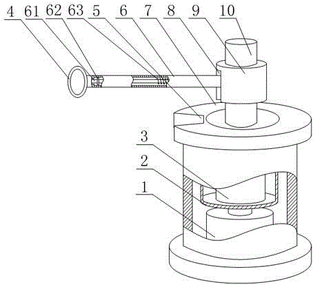
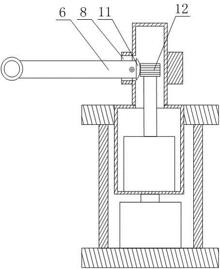
[0021] Such as figure 1 and figure 2 As shown, this embodiment includes a hollow cable reel 7 and a motor 1 fixed in the cable reel 7, the output end of the motor 1 is connected with a positioning cylinder 2, the upper end of the positioning cylinder 2 penetrates the upper end surface of the cable reel 7, and A cylinder 3 is installed in the positioning cylinder 2, and a rotating cylinder 10 communicating with it is fixed on the upper end surface of the positioning cylinder 2. The side wall of the rotating cylinder 10 is provided with a rectangular gap, and is hinged in the gap. There is a guide rod 6, and a plurality of ring teeth 12 are arranged on the output end of the cylinder 3. One end of the guide rod 6 is provided with a fan-shaped tooth 11 that matches the ring teeth 12, and the inside of the guide rod 6 is provided with a cavity. The end of the rod 61 is connected to the inner wall of the cavity by a spring 63, the movable end of the push rod 61 runs through the ot...


PUM


Abstract

The invention discloses a central tube type ADSS (All-Dielectric Self-Supporting) optical fiber cable take-up machine which comprises a cable tray and a motor, wherein the output end of the motor is connected with a positioning cylinder, the positioning cylinder is internally provided with an air cylinder, the upper end surface of the positioning cylinder is fixedly connected with a rotating cylinder communicated with the interior of the positioning cylinder, and the output end of the air cylinder is provided with multiple annular teeth; one end of a guide rod is provided with fan-shaped teeth matched with the annular teeth, the guide rod is internally provided with a cavity, and the tail end of the top rod is connected with the inner wall of the cavity by virtue of a spring; the inner wall, which is close to one side of a guide ring, of the cavity is provided with an annular bulge, and the movable end of the top rod is fixedly provided with a limiting block which is matched with the annular bulge; the guide ring can limit an optical fiber cable, the optical fiber cable is prevented from bouncing during a moving process; meanwhile, by virtue of the up-and-down movement of the guide rod, the swing range of the optical fiber cable can be buffered, after the optical fiber cable enters into the cable tray, a relatively stable state of the cable tray is ensured, distribution of each layer of the optical fiber cable on the cable tray is more uniform, and the two adjacent loops of optical fiber cable can be closely attached together.

Description

technical field [0001] The invention relates to the field of optical cable laying, in particular to a central tube type ADSS optical cable take-up machine. Background technique [0002] In daily life, optical fibers are used for long-distance information transmission because the loss of light in optical fibers is much lower than that of electricity in wires. Most optical fibers must be covered by several layers of protective structures before use. The coated cable is called an optical cable. The protective layer and insulating layer on the outer layer of the optical fiber can prevent the surrounding environment from harming the optical fiber, such as water, fire, electric shock, etc. . [0003] During the long-distance laying of optical cables, due to the influence of various factors, some of the pulled out optical cables need to be recycled. In the prior art, due to the distance factor, the optical cables are usually manually rotated when the cable is pulled to achieve the...

Claims


Application Information

Patent Timeline
Patent Type & Authority Applications(China)
IPC IPC(8): B65H54/30B65H57/06B65H75/28
Inventor 孙义兴王耀明许建国彭志勇刘东李涛
Owner 成都亨通光通信有限公司
Why Eureka
Try Eureka