Automatic exhaust valve device

A technology of automatic exhaust valve and exhaust port, applied in the direction of valve device, valve operation/release device, valve details, etc., can solve the problem of increasing processing difficulty and production cost, failure of automatic exhaust valve, and affecting the sealing of gas outlet and other issues, to achieve the effect of long-term stable performance, simple and convenient installation and use, and elimination of potential safety hazards

Pending Publication Date: 2019-02-22
湖南省上池环保科技有限公司
View PDF1 Cites 0 Cited by
  • Summary
  • Abstract
  • Description
  • Claims
  • Application Information

AI Technical Summary

Problems solved by technology

[0004] Although the above-mentioned automatic exhaust valve can automatically release the air in the pipeline to a certain extent, but: 1. After using for a period of time, the elastic force of the spring is weakened due to the long-term elastic state, which causes the float to not return in place, which seriously affects the gas flow. The tightness of the outlet, when the airtightness of the gas outlet decreases, it will cause air to enter the original air-free pipeline, and cause the oil in the pipeline to leak out, and even cause major safety accidents; 2. The return spring is easily damaged, causing the automatic The exhaust valve fails; 3. The space in the automatic exhaust valve is small, and the installation and maintenance of the spring are difficult; 4. One end of the float is hinged in the cavity wall, and the float moves in a circle around its hinge point within a certain range. The tightness of the gas outlet and the accuracy of the position of the hinge point are quite high, which increases the processing difficulty and production cost; 5. When the hinge point rotates, it is affected by the gravity of the float and the spring force, which causes the force and friction of the hinge point to increase. , after the float moves frequently, it will cause the hinge point to be worn and deformed, and at the same time cause the position of the float (such as the horizontal state of the float to be deflected) and the rotation action to deviate, which will seriously affect the sealing of the float and the gas outlet; 6. When the pipeline When there is oil flowing inside, the flowing oil will generate suction. When the oil flow rate is high, the suction will be greater. When the suction acts on the float downward, the float is likely to be affected by this suction. Moving downwards, thereby opening the upper gas outlet, resulting in oil leakage or air entering the pipeline from the gas outlet instead, so that the gas in the pipeline does not decrease but increases, which increases safety hazards

Method used


Image

  • Automatic exhaust valve device
  • Automatic exhaust valve device
  • Automatic exhaust valve device

Examples


Embodiment Construction

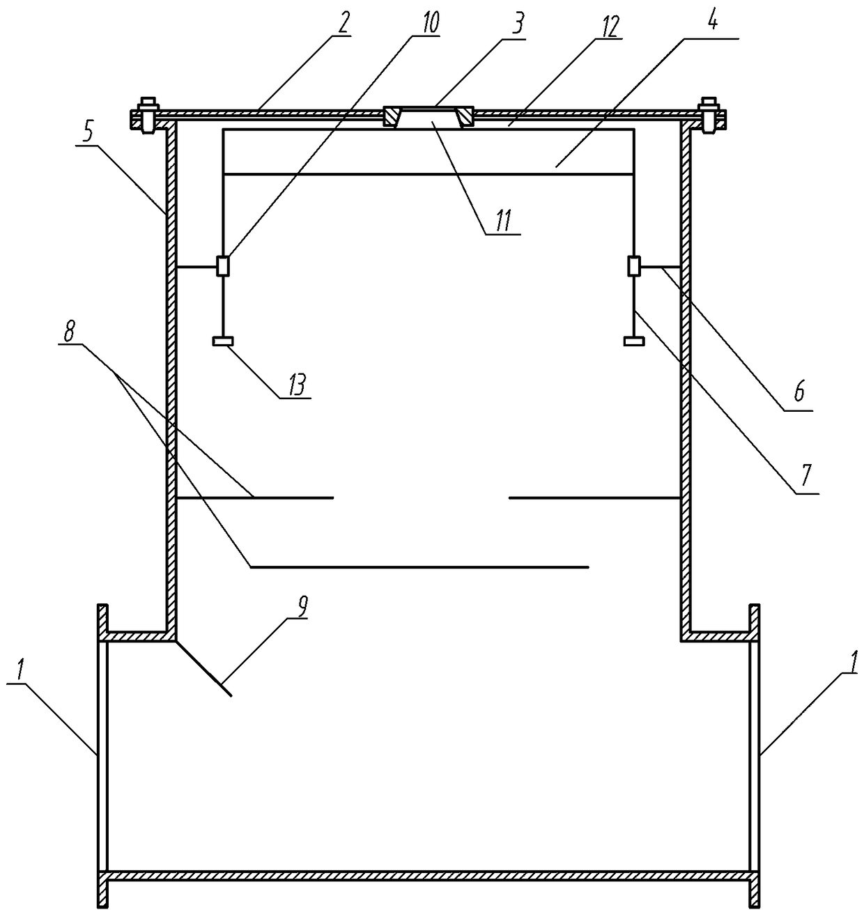
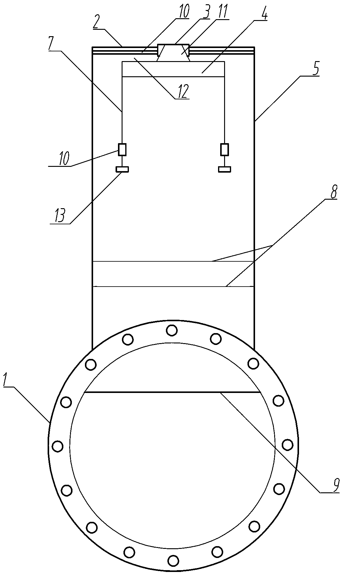
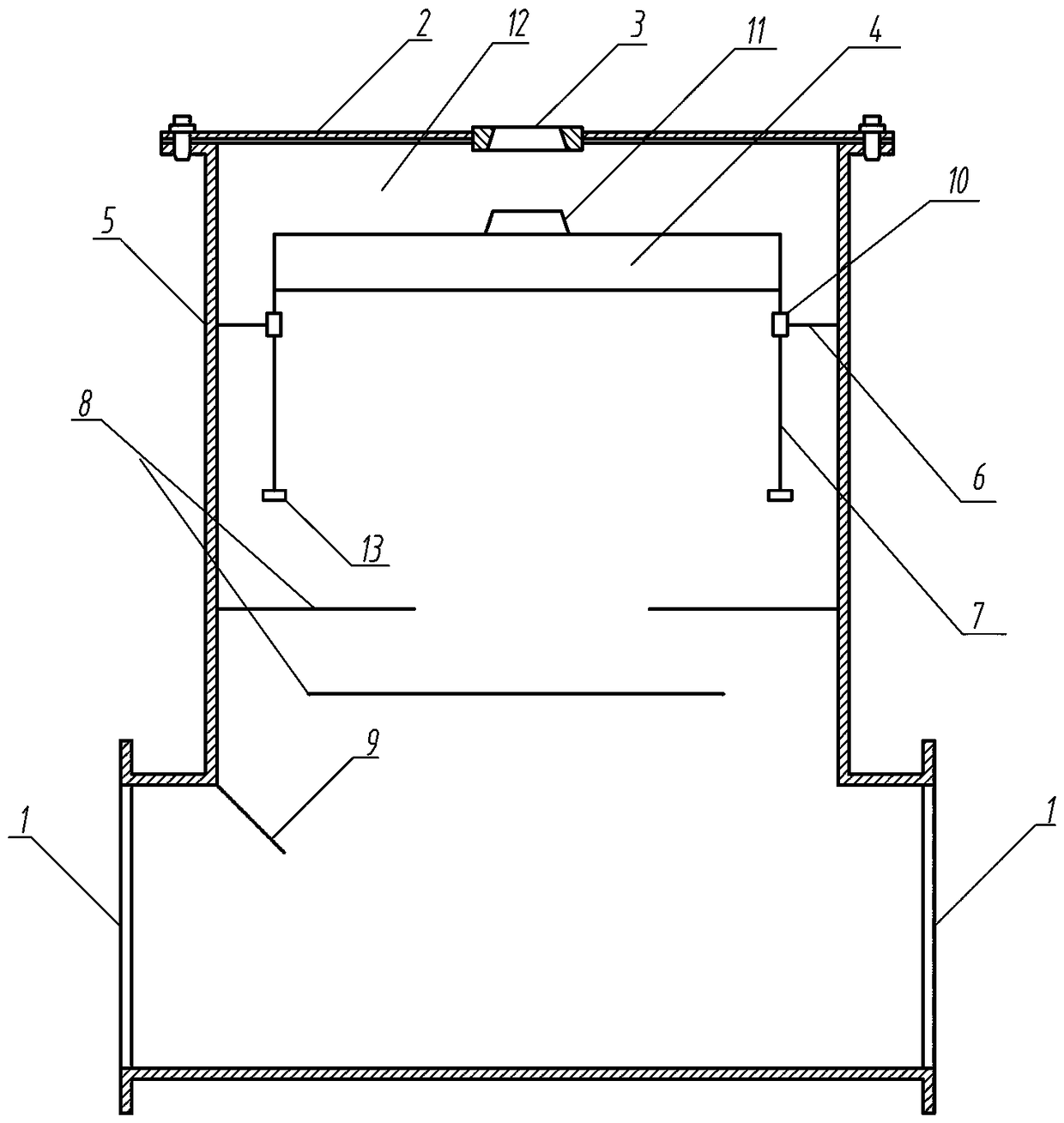
[0022] Below in conjunction with accompanying drawing the specific embodiment of the present invention is described in detail as follows:

[0023] See attached Figure 1-5 As shown, the automatic exhaust valve device includes a hollow valve body 5 in which one end communicates with the outlet pipeline of the oil storage tank through a flange 1, and the other end communicates with the pipeline of the floating oil outlet device through a flange. The center of the top of the body is provided with an exhaust port 3, and a sealing device is provided below the exhaust port in the valve body, which is characterized in that the sealing device is a structure that can slide up and down in the cavity of the valve body below the exhaust port, which is mainly composed of Float 4, slide rail 7, slide rail track 10 and track fixing frame 6 are assembled and constituted, and described float is a hollow sealed cavity structure, and the top of float is provided with the stopper 11 that matches ...


PUM


Abstract

The invention discloses an automatic exhaust valve device. A valve body with the top end center provided with an exhaust port is included. The valve body is internally provided with a sealing device.The automatic exhaust valve device is characterized in that the sealing device is of a structure capable of sliding up and down in a cavity of the part, below the exhaust port, of the valve body and is mainly formed through assembling of a floater, sliding rails, sliding rail tracks and track fixing frames; a blockage part is arranged at the top end of the floater, and a gap is arranged between the top end of the floater and the top wall of a hollow cavity of the valve body; and the multiple sliding rails are vertically and evenly arranged at the bottom end of the floater, the sliding rail tracks are connected to the inner wall of the valve body, and a plurality of liquid discharging stop plates are further arranged below the sealing device. The automatic exhaust valve device effectively achieves the function of automatic pipeline gas discharging, the abnormal motion of a floating oil discharging device due to gas in a pipeline is avoided, and potential safety hazards existing in a storage tank due to the pipeline gas are eliminated. The structure is simple, the production cost is lower, installation and usage are simpler and more convenient, the long-term work performance is stable and reliable, and safety of the oil tank and the pipeline is ensured.

Description

technical field [0001] The invention belongs to the field of petroleum equipment, in particular to an automatic exhaust valve safety protection device used in conjunction with a floating oil discharge device of a petroleum storage tank. Background technique [0002] According to the requirements of the petrochemical light oil storage tank industry standard "Design Standards for Vertical Cylindrical Steel Welded Oil Tanks", a floating oil outlet device should be installed in the oil tank. The floating oil delivery device is suitable for the use of fuel delivery and supply systems with high oil quality, short oil settling time, and fast surroundings of oil tank equipment. Compared with the traditional oil delivery at the bottom of the oil tank, the floating oil delivery device of the oil tank uses moisture The sedimentation principle in the gravity field gives priority to the upper layer of high-quality clean fuel, so as to ensure that the fuel delivered reaches the best quali...

Claims


Application Information

Patent Timeline
Patent Type & Authority Applications(China)
IPC IPC(8): F16K31/22F16K33/00F16K27/02
CPCF16K31/22F16K27/02F16K33/00
Inventor 吴奇成李修
Owner 湖南省上池环保科技有限公司
Why Eureka
Try Eureka